3.
Stage 2
Vertical Delivery Pipe Assys Installation Procedure
Components Supplied by PEC
Front & Rear Vertical Pipe Assys
Head Cabinet Assy. (Fitted with Grade ID Decals)
Head Cabinet mtg. Brkts
Flexible Safety Hose Assys
External Hose Assy, fitted with Nozzles, Grade Covers & Gas Guards
Nozzle Grade ID Decals
Vent Box Assy Front & Rear (2 x Top Caps)
Serial Name Plate. (Name Plate to be Adhered to Top LH corner of GRP head access Door)
•
Installation Procedure
•
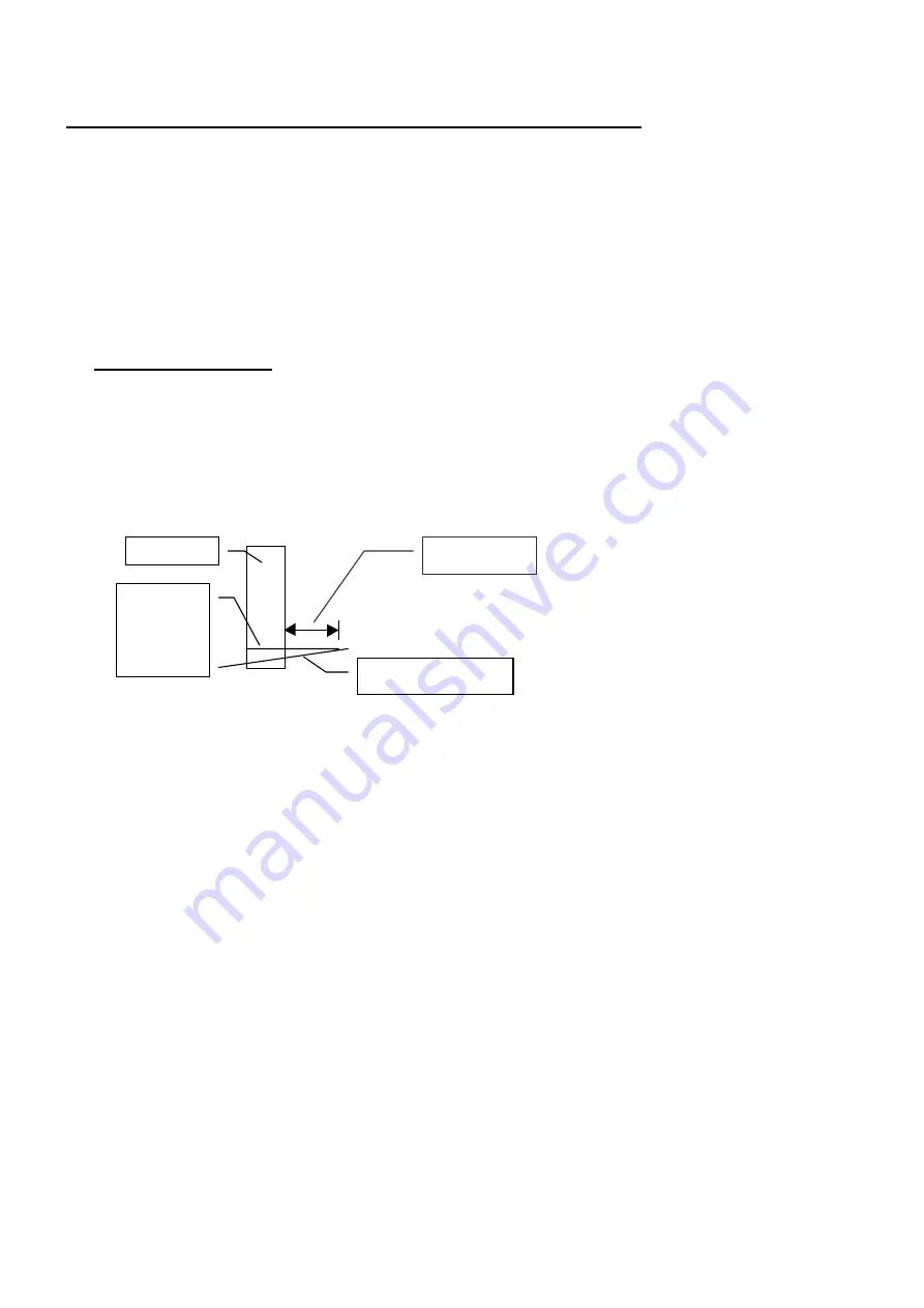
Using a Sprit level find the highest point on Forecourt out to a distance of 160 mm from Main
Column(in any direction).Transfer this point onto Front face of Column (Front =Sump @ right hand
side of Column) clearly mark as datum point on Column Face. (This is a datum point to start
measuring from regards positions of components & mtg. brkts. etc. (See Sketch below) This point
must be established to obtain mounting heights & ground clearances etc. for Final Cladding.
•
From the above, mentioned Datum Line, transfer & mark a point 2.3 m Vertically up Column. If
preferred a second but lower point could be marked @ 1.405m.up Having both these Datum points
marked on Column could be advantageous as they could then both serve as a double checks. Note:
Marks should be made Horizontally, as they will later be used to align Vertical Pipe & Holster Assy
Mtg. Brkts. etc. (Details refer Fig 4 )
•
Place Front Vertical Pipe Assy 89826 onto front face of Column, top angled section of Pipe Assy.
should be pointing out to right hand side. (eg. towards Sump ) (Note: Front of Dispenser = Column on
Left with Sump on Right) Both of the middle two Mounting brkts on Vertical Pipe Assy have a right
angle Lug welded to them, these Lugs are location lugs & should be positioned up against right hand
face of column.
•
With Lugs positioned against Column side face, slide Pipe Assy up until top face of second horizontal
Brkt. up Assy aligns with lower mark 1405.4mm Son Column and/or top face of second horizontal
Brkt. down Assy aligns with upper mark on Column. Secure into position with “G” or “F” Clamps.
(Or Ratchet Ties)
•
Check Column Stops on second & third horizontal brkts are hard against Column Face, also check
Vertical Pipe Assy is vertical. (If not this could indicate Column is not truly Vertical, in this instance
move either top or bottom of Pipe Assy. to obtain true Vertical reading, secure Clamps, recheck
heights from Forecourt datum marks.
160 mm
Column
Mark
Level
on
Column
Forecourt
Summary of Contents for Apollo 3000
Page 1: ...Apollo 3000 Set up Installation Parts Manual...
Page 2: ......
Page 4: ......
Page 15: ...11 Float Switch 89778 Float Swt Mtg Angle only 89749 Float Switch Bracket Assembly...
Page 26: ...22 Stage 1 Installation Procedure Sump Column Position Fig 2...
Page 27: ...23 file gme c docum pec apollo2 fig 2 manual doc Stage 1 Installation Service Area Spec Fig 3...
Page 28: ...24 Stage 1 Installation Procedure Mounting Positions Fig 4...
Page 29: ...25 Stage 3 Vent Box Installation Vent Box Position Sealing Spec Fig 5...


