background image

Garden & Pond kit M10 Roadmap


Planning


Proper preparation is important. First make a sketch of your fence and determine whether you have enough 
materials to make the fence. Follow the steps below for a fast and successful installation of your electric fence.  


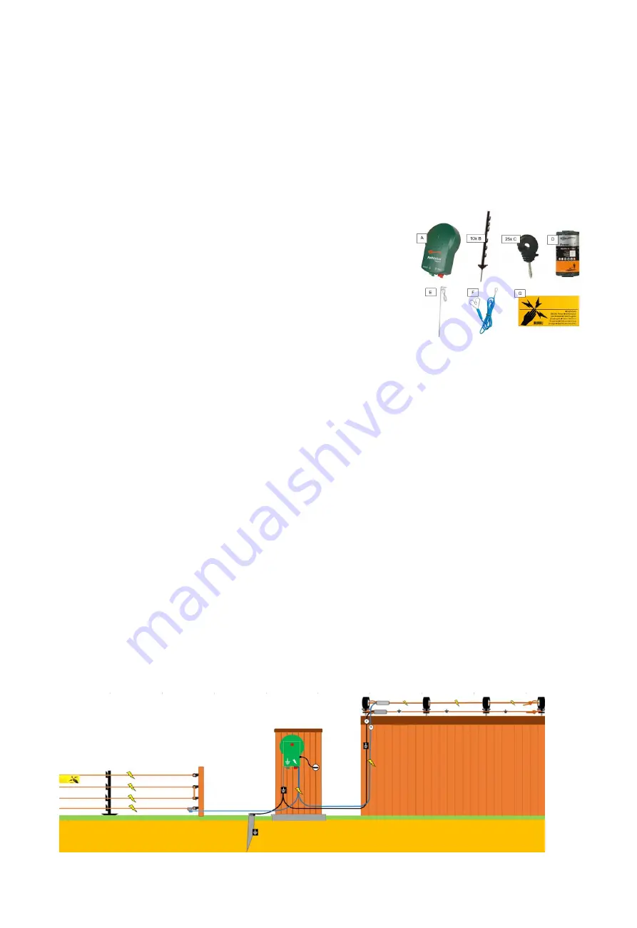
Contents of the kit  

(A) 1 pc. Electric fence device M10  
(B) 10 pcs. Plastic fence posts (terra)  
(C) 25 pcs. Ring insulators  
(D) 1 roll 100m Vidoflex (conductive) wire (green)  
(E) 1 pc. Earth pin 0.5 meter including 3 meter cable.  
(F) 1 pc. Fence connection cable with clip and ring eye  
(G) 1 pc. Warning sign 
(H) 4 pcs. Vidoflex connector  


Determine the type of fence  

We distinguish two types of electric fencing, 


It

’s important to know that a shock is only felt when the animal touches the earth at the same time as it 

touches the electric fence, as this completes the circuit.  

 
1. The basic system: 

This system is easy to build with (plastic or wooden) posts that are placed in the earth.  
The wires in the fence are connected to the electric fence device thanks to a fence connection cable. The 
earthing device is grounded thanks to an earth pin in the ground.  
With simultaneous contact of the wire and the ground underneath, the circuit is closed and a shock will be felt.  
For the explanation of this type of installation, go to:  

Part 1

 – Electric fence for garden, yard, ponds or around the aviary 

in this manual.  

 
2. A plus/minus system: 

This


system is needed when the wire in the fence is placed at a higher height, such as a fence on a barrier, 

wall or in the gutter.  
If you place a wire over a fence, an extra wire will always have to be placed for grounding, also known as the 
Plus/Minus system.  
In such a system, the wires in the fence are connected alternately directly to the electric fence device. The 
placement of an earth pin 

isn’t necessary in such a system.  

As soon as at least one plus and one minus wire are touched simultaneously, the circuit will be closed and a 
shock will be felt.  
For the installation explanation of such a system goes to:  

Part 2

 – Electric plus/minus fence on (garden) barrier or wall


3. A combination of both systems: 


A combination of both systems is also possible, of course, follow both the instructions in part 1 and the 
instructions in part 2 of this step-by-step plan.  


Summary of Contents for Garden & Pond kit M10

Page 1: ...ing the earth pin and grounding 4 Step 6 Connecting the fence 5 Step 7 Switch on and test electrical installation 5 Part 2 Electric plus minus fence on a garden barrier or wall 6 Step 1 Required mater...

Page 2: ...on cable The earthing device is grounded thanks to an earth pin in the ground With simultaneous contact of the wire and the ground underneath the circuit is closed and a shock will be felt For the exp...

Page 3: ...s here Step 2 Determine the desired height of your fence We recommend a 2 wire fence for small dogs a 3 to 4 wire fence for large dogs and a 3 wire fence for cats The distances between the wires depen...

Page 4: ...to the starting post continue this process for each post and next wire height Hook the wire through a loop attached with a Vidoflex wire connector in the last insulator or wire holder do not tighten t...

Page 5: ...nection cable F is a heart shaped clip you connect the wire of the fence with the electric fence device with this clip Slide the heart shaped clip over the wire D and then move the clip F1 sometimes h...

Page 6: ...r a wooden fence surface The supplied ring insulators C are provided with self cutting threads for among other things wood which makes them relatively easy to drill into soft wood without pre drilling...

Page 7: ...xt to last ring insulator 5 Attach the wire to the last insulator and follow steps 1 to 3 as described above again 6 Now cut off any excess wire right behind the sealed Vidoflex wire connector Step 4...

Page 8: ...insulation layer of the Gallagher ground cable Y 2 Remove the cover plate from the Vidoflex connector H on wire D1 by removing the 2 nuts 3 Then place the stripped part of the ground cable Y1 in the...

Page 9: ...en turn the knob on the thread again and tighten the knob firmly hand tight Connecting the Plus cable 1 Strip the end of the ground cable Y2 according to the instructions in chapter 5 2 Now repeat the...

Page 10: ...nce has been placed there has been contact between the pet and the fence This way your pet immediately learns that the fence is forbidden to pass Important information Warning Read and understand all...

Reviews: