30
Gallagher 3E1164 Power Fence Systems User Manual
Installing a Permanent Power Fence
TM
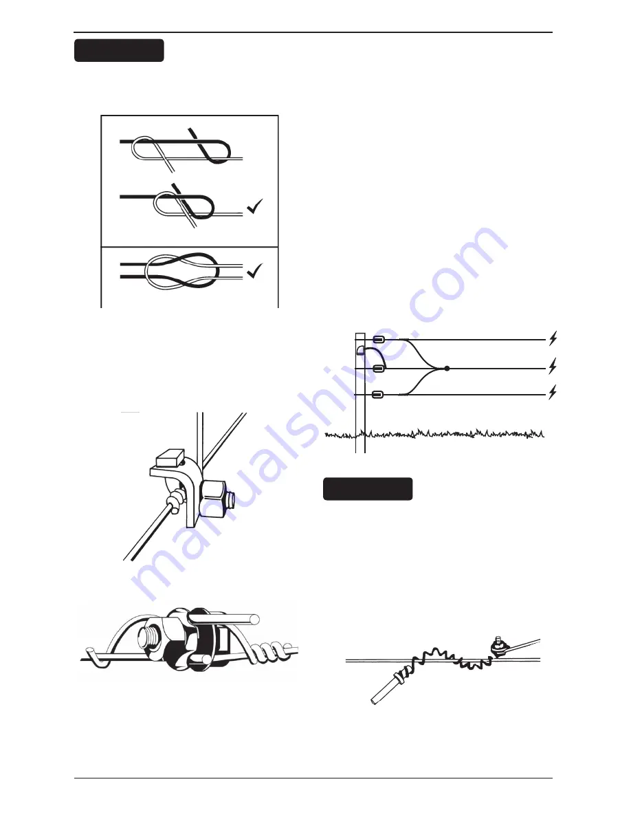
Join wire using a figure eight or reef knot.
These will give better electrical contact
than a double loop join.
Figure 4.23(a)
All other permanent connections should
be clamped using Joint Clamps (G603), see
Figures 4.23a and 4.23b
, to ensure tight
wire connections.
Figure 4.23(b)
Figure 4.23(c)
Electrical connections
Connect all live wires in parallel at
both ends of the fence. This will ensure
maximum conductivity. For a three wire
fence, bring the tails, previously left long
(refer to section “
Position the line posts
and wires
” under section
4.4.2 Building
the fence
) from the top and third wires to
the second wire and connect firmly with a
Joint Clamp (G6030 or G6035), see
Figure
4.23
. Make sure it’s tight. Wrap the excess
wire around this second wire and break it
off for a smooth, tidy finish. Bring the tail
from the second fence wire to a Gallagher
Cut Out Switch (G6076 and G6087), see
Figure 4.29
where necessary, otherwise
break it off. This wiring configuration
minimises the number of joint clamps
required and creates a tidy installation.
Figure 4.24
Attaching a Flexible Connector (G6050)
to the lower wires means you can easily
disconnect them at times when there is
high vegetation growth. Make a loop
on the tail of each wire, adjacent to the
wire above it, and attach the Flexible
Connector. Connect it to a powered wire
as shown.
Figure 4.25
G6033
G6035
Step 1
Step 2
Figure of eight knot
Reef knot
G607
G603
HANDY HINT
HANDY HINT


