46
Gallagher 3E1164 Power Fence Systems User Manual
Safety Requirements and Regulations
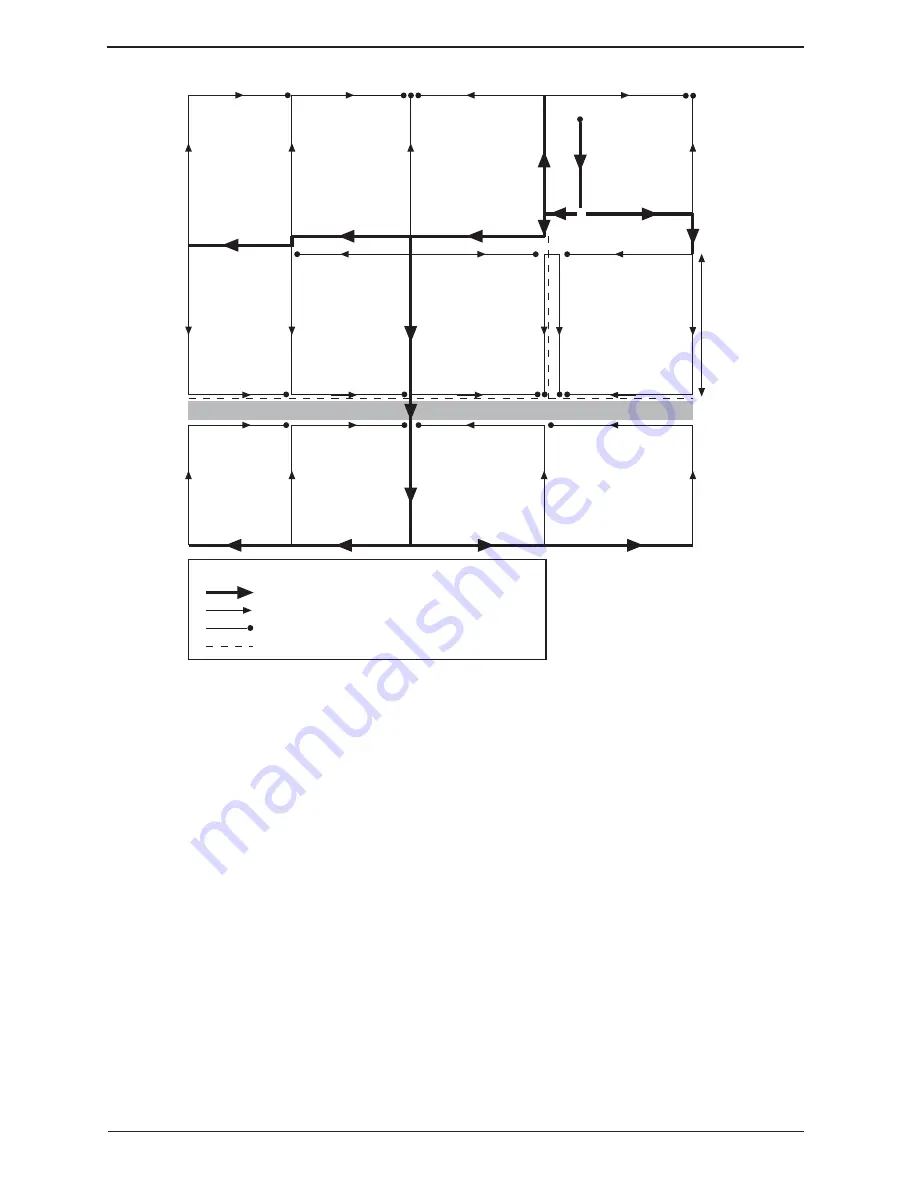
Figure 8.5 shows an improved fence design for the same property.
1. Keep the energizers and main
feeders at least 100m away from
communication cables or lines.
2. Make sections of the fence that are less
than 100m away as short as possible
and leave them open-circuited at the
far end, (i.e. nothing connected to the
far end).
3. Make sure that the electric fence earth
is separate from all other earthing
systems, is as short as possible, and is
routed away from communication lines
or cables.
4. Consider the installation of switches
in the feed to each paddock to enable
sections of the fence to be isolated to
assist in fault location.
5. A flood gate controller should be
installed in series with the lead to
floodgates to ensure that they do not
put a hard earth fault on the fence
when the water rises.
6. Use of a Smartfix (G5090) is
recommended to easily check for
higher current levels in the fence which
indicates faults.
7. A well-maintained electric fence will
draw approximately 1 to 2 amps of
current for each kilometre of electrified
fence line. If the current in the fence
exceeds this then it should undergo
maintenance to remove shorts and/or
overgrowth.
D
R
I
V
E
W
A
Y
ROAD
RACE
X
ENERGIZER
150m
EARTH
ELECTRODE
High current section of the electric fence
Low current section of the electric fence
Low current dead-end section of the electric fence
Telephone cable
KEY
Figure 8.5


