background image


3Ennnn Gallagher T30 Reader Installation Note| DRAFT2 | July 2020 
Copyright © Gallagher Group Limited 

Page 4 

1


Introduction 

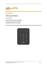
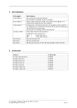
The Gallagher T30 Keypad Reader is available in a variety of variants.  The variant you have purchased 
determines the available functionality and supported technologies for the reader.   

The Multi Tech variants C300490 and C300491 support Gallagher mobile credentials, using Bluetooth® 
low energy technology. 

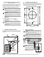
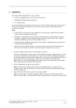
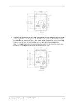
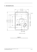
The reader can be mounted on a rectangular 50 mm x 75 mm (2 in x 3 in) flush box, a BS 4662 British 
Standard square flush box, or any solid flat surface 

The terminal sends information to the Gallagher Controller and acts upon information sent from the 
Gallagher Controller.  The terminal itself does not make any access decisions. 

2


Before you begin 

2.1


Shipment contents 

Check the shipment contains the following items: 


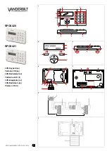
1 x Gallagher T30 Keypad Reader facia assembly 


1 x Gallagher T30 Keypad Reader bezel 


2 x 6-32 UNC (32 mm) Phillips drive fixing screws 


2 x M3.5 (40 mm) Phillips drive fixing screws 


5 x 25 mm No.6 self tapping, pan head, Phillips drive fixing screws 


1 x M3 Torx Post (T10) Security screw 

2.2


Power supply 

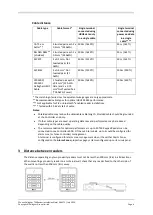
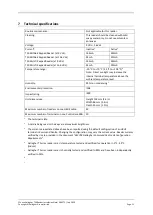
The Gallagher T30 Keypad Reader is designed to operate over a supply voltage range of 9 - 16 
Vdc measured at the readers.  The operating current draw is dependent on the supply voltage at 
the reader.  The power source should be linear or a good quality switched-mode power supply.  
The performance of the reader may be affected by a low quality, noisy power supply. 

2.3


Cabling 

The Gallagher T30 Keypad Reader requires a minimum cable size of 4 core 24 AWG (0.2 mm

2

stranded security cable.  This cable allows the transmission of data (2 wires) and power (2 wires).  
When using a single cable to carry both power supply and data, both the power supply voltage 
drop and data requirements must be considered.  Although the reader is specified to operate at 
9 Vdc, for good engineering design it is recommended that the voltage at the reader should be 
approximately 12 Vdc. 

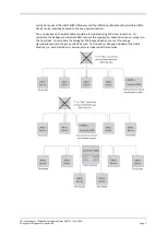
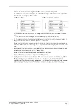
 HBUS cabling topology 

The HBUS communications protocol is based on the RS485 standard and allows the reader to 
communicate over a distance of up to 500 m (1640 ft). 

The cabling between HBUS devices should be done in a "daisy chain" topology,  
(i.e. A "T" or "Star" topology should not be used between devices).  Should "Star" or "Home-Run" 

Summary of Contents for T30

Page 1: ...y 2020 Copyright Gallagher Group Limited Page 1 Gallagher T30 Keypad Reader Installation Note T30 MULTITECH Keypad Reader Black C300490 T30 MULTITECH Keypad Reader White C300491 T30 MIFARE Keypad Read...

Page 2: ...mpleteness and it should not be relied on as such To the extent permitted by law all express or implied or other representations or warranties in relation to the information are expressly excluded Nei...

Page 3: ...ted Page 3 Contents 1 Introduction 4 2 Before you begin 4 2 1 Shipment contents 4 2 2 Power supply 4 2 3 Cabling 4 3 Distance between readers 6 4 Installation 7 5 LED indications 10 6 Accessories 10 7...

Page 4: ...hillips drive fixing screws 1 x M3 Torx Post T10 Security screw 2 2 Power supply The Gallagher T30 Keypad Reader is designed to operate over a supply voltage range of 9 16 Vdc measured at the readers...

Page 5: ...one physical location The end devices on the HBUS cable should be terminated using 120 ohms resistance To terminate the Gallagher Controller 6000 connect the supplied on board termination jumpers to...

Page 6: ...types for optimal HBUS RS485 performance Not applicable for PIV or Bluetooth enabled reader installations Tested with 13 6V at start of cable Notes Shielded cable may reduce the obtainable cable leng...

Page 7: ...r screws must be used as well as the flush box screws Without corner screws the top of the product is vulnerable to separation from the wall 1 Ensure the building cable has been run out through the fl...

Page 8: ...rner fixing screws provided Secure the tamper tab located in the bezel to the mounting surface using the remaining fixing screw provided It is important the four corner fixing screws are used to ensur...

Page 9: ...n into the bezel Note Ensure that there is no pressure upon the wire set as it exits the terminal Ensure the wire set does not exit the reader at a sharp angle as this may compromise the integrity of...

Page 10: ...Controller but the terminal has no Alarm Zone s assigned to the Alarms Zones property page The terminal screen displays the text Not configured On Green or Red Fully configured and functioning normall...

Page 11: ...vel Humidity 95 non condensing5 Environmental protection IP68 Impact rating IK09 Unit dimensions Height 118 mm 4 6 in Width 86 mm 3 4 in Depth 25 mm 1 0 in Maximum number of readers on one HBUS cable...

Page 12: ...o provide reasonable protection against harmful interference in a residential installation This equipment generates uses and can radiate radio frequency energy and if not installed and used in accorda...

Page 13: ...nnn Gallagher T30 Reader Installation Note DRAFT2 July 2020 Copyright Gallagher Group Limited Page 13 9 Mounting Dimensions IMPORTANT This picture is not to scale therefore use the measurements provid...

Reviews: