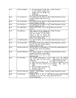
3-7. LCD Operation
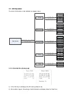
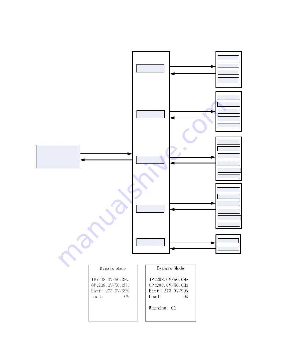
The entire LCD structure is demonstrated as diagram below:
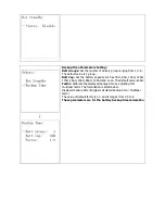
Main Interface
Control
Measurement
Information
Setting
Alarm
Page 1: Input
Page 2: Output
Page 3: Battery
Page 4: Bypass
Page 5: Charger
Turn On
Batt Test
Mute
Para Unlock
Page 1: Bypass
Page 2: ECO
Page 3: Output
Page 4:Battery
Page 5:
UPS
Info
Page 6: Others
Fault Info
Warning Info
Bypass
ECO
Output
Battery
Calibration
Others
Press button
“
Enter
”
Press button
“
Enter
”
Press button
“
Enter
”
Press button
“
Enter
”
Press button
“
Enter
”
Press button
“
ESC
”
Press either button
“
UP
”
or
“
DOWN
”
Press button
“
Esc
”
Press button
“
Esc
”
Press button
“
Esc
”
Press button
“
Esc
”
Press button
“
Esc
”
3-7-1. Main interface (home page)
1)
In the first line, it will display the UPS running status mode;
2)
When alarms happen, the warning or fault information will display below the “load” line;


