6
FC66000611 - 07
È severamente vietata la riproduzione anche parziale di questo manuale / All copying, even partial, of this manual is strictly forbidden
5.2
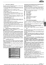
INSTALLATION FOR THE FC,FF,FP,FU MODEL
WARNING: The FC, FF built-in models must not be accessible
to the public
The air outlets should not be placed immediately under a socketFor the
FC,
FF
flush-mounted model, perform the connection between the fan coil and
the ducts, and place damping material between the duct and the unit.
The ducts, in particular the outlet ones, must be insulated.
In order to avoid air back suction on the fan coil, keep a minimum distance
between the air outlet and recovered air flow as shown in figure 5 page
29.
The minimum installation height should not be lower than 1.8 metres from
floor level. Provide for an inspection port to the unit.
5.3
ELECTRICAL CONNECTIONS
Carry out the electrical wiring after having turned the power off
in
compliance with the current safety regulations
following the
diagram of the figure 6 and its caption.
Check that the power supply corresponds to the rated power reported
on the unit nameplate.
Electric connections in dotted lines should be carried out by the installer.
An omnipolar mains isolator in overvoltage category III must be present for
every fan coil in the power supply line.
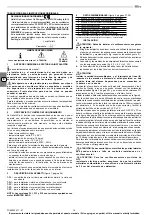
On the wiring diagram the following abbreviations are used:
MODELS WITH 6-SPEED MOTORS (FIGURE 7)
The connections indicated must be made by the installer.
Make the electrical connections with the power supply
disconnected, in accordance with current safety regulations.
Check that the mains electricity supply is compatible with the
voltage shown on the unit rating plate.
Each fan coil requires an individual electric socket and a switch
with a suitable safety fuse.
BK
Black, speed 6
BU
Blue, speed 5
GY
Grey, speed 4
BN
Brown, speed 3
V T
Purple, speed 2
RD
Red, speed 1
CN
Fast-on connector
F
Safety fuse (not supplied)
IL
Circuit breaker (not supplied)
M
Fan motor
WH
White = common
6
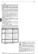
TEST RUN
Check that the unit is perfectly levelled and that the drain pipe is not
obstructed (rubble deposits, etc.).
Check that the water connections (to the heat exchanger and water
drainage) are sealed.
Check that the electrical wiring is perfectly tight.
Be sure that the air purge of the heat exchanger has been carried out.
Replace the cabinet (where existing).
Turn on the power supply and check the unit running.
7
USE
To use the fan coil unit, refer to the instructions of the control panel,
available as accessory.
Air outlet grids on the cover cabinet (FL, FP and FU) can be turned 180°
to direct the flow into the room or towards the wall on which the unit is
mounted.
The grids and the side doors are snapped onto the cabinet. Before
removing them in order to change their position, cut the power off and wear
protective gloves.
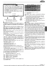
BK
Black = max. speed
BU
Blue = medium speed
CN
Fast-on connector
F
Fuse, not supplied
GNYE
Yellow/Green = earth
IL
Line switch, not supplied
M
Motor
RD
Red = min. speed
WH
White = common
1
To command (accessory)
8
MAINTENANCE
WARNING: Maintenance must only be carried out by an
assistance centre authorised by the manufacturer or by qualified
personnel.
For safety reasons before carrying out any maintenance or
cleaning operation, switch off the unit turning the selection
switch to “Stop” and the power supply switch on position 0 (OFF).
Be careful during any maintenance operation; you could get
injured by some metal parts; use protective work gloves.
The estro fan coils do no require any particular maintenance operation:
only the periodical cleaning of the air filter should be carried out.
It is necessary to carry out a running in period of 100 hours in order to
eliminate all mechanical friction.
The starting up must be carried out at the maximum speed.
For good operation of the estro fan coils follow the instructions below:
- keep the air filter clean;
- do not pour liquids into the unit;
- do not introduce metal parts through the air outlet grid.
- keep the air inlet and outlet free at all times.
Each time the machine is turned on after being idle for a long period, ensure
there is no air in the heat exchanger.
Before using the unit for air conditions, check that:
- condensate drainage is performed correctly:
- the heat exchanger fins are not obstructed by deposits of dirt.
If necessary clean the fins with low pressure compressed air or steam
without damaging them.
9
CLEANING
WARNING: The filter must only be cleaned by an assistance
centre authorised by the manufacturer or by qualified personnel.
For safety reasons before carrying out any maintenance or
cleaning operation switch off the unit turning the selection
switch to “Stop” and the power supply switch on 0 (OFF).
Clean the filter at least once a month and in any case before using the unit
(before the heating or the air conditioning season).
For cleaning the air filter proceed as follows (figure 8, page 32):
- model
FL
: turn the screws 90°, which secure the filter to the cover
cabinet, to 1/4 turn and remove the filter;
- model
FP
: Unscrew the screws holding the filter to the cabinet and
remove the filter;
- model
FF
: Unscrew the screws to remove the platelets, and remove the
filter
- flush-mounted model
FC
: reach the fan coil through the inspection panel
and remove the filter, turning the locking brackets 90°;
- model
FU
: remove the air filters that are inside the intake grids located
on the front panel of the cover cabinet;
- clean the filter with lukewarm water , or in case of dry dust, with
compressed air;
- reassemble the filter after having dried it up.
It is recommended to replace the air filter yearly, and to use original spare
parts.; the fan coil model is reported on the nameplate located on the
internal part of the side panel of the unit.
To clean the unit cabinet proceed as follows:
- use a soft cloth;
- do not pour any liquid on the unit, as this could cause electrical shocks
or damage the components inside it;
- do not use any aggressive chemical solvents; do not use very hot water
to clean the air outlet grid.
GB


