background image

6

FC66000611 - 07

È severamente vietata la riproduzione anche parziale di questo manuale / All copying, even partial, of this manual is strictly forbidden

5.2

INSTALLATION FOR THE FC,FF,FP,FU  MODEL

WARNING: The FC, FF built-in models must not be accessible

to the public

The air outlets should not be placed immediately under a socketFor the 

FC,

FF

 flush-mounted model, perform the connection between the fan coil and

the ducts, and place damping material between the duct and the unit.
The ducts, in particular the outlet ones, must be insulated.
In order to avoid air back suction on the fan coil, keep a minimum distance
between the air outlet and recovered air flow as shown in figure 5 page
29.
The minimum installation height should not be lower than 1.8 metres from
floor level. Provide for an inspection port to the unit.

5.3

ELECTRICAL CONNECTIONS

Carry out the electrical wiring after having turned the power off 

in

compliance with the current safety regulations 

following the

diagram of the figure 6 and its caption.
Check that the power supply corresponds to the rated power reported
on the unit nameplate.
Electric connections in dotted lines should be carried out by the installer.
An omnipolar mains isolator in overvoltage category III must be present for
every fan coil in the power supply line.
On the wiring diagram the following abbreviations are used:

MODELS WITH 6-SPEED MOTORS (FIGURE 7)

The connections indicated must be made by the installer.
Make the electrical connections with the power supply
disconnected, in accordance with current safety regulations.
Check that the mains electricity supply is compatible with the
voltage shown on the unit rating plate.
Each fan coil requires an individual electric socket and a switch
with a suitable safety fuse.

BK

Black, speed 6

BU

Blue, speed 5

GY

Grey, speed 4

BN

Brown, speed 3

V T

Purple, speed 2

RD

Red, speed 1

CN

Fast-on connector

F

Safety fuse (not supplied)

IL

Circuit breaker (not supplied)

M

Fan motor

WH

White = common

6

TEST RUN

Check that the unit is perfectly levelled and that the drain pipe is not
obstructed (rubble deposits, etc.).
Check that the water connections (to the heat exchanger and water
drainage) are sealed.
Check that the electrical wiring is perfectly tight.
Be sure that the air purge of the heat exchanger has been carried out.
Replace the cabinet (where existing).
Turn on the power supply and check the unit running.

7

 USE

To use the fan coil unit, refer to the instructions of the control panel,
available as accessory.
Air outlet grids on the cover cabinet (FL, FP and FU) can be turned 180°
to direct the flow into the room or towards the wall on which the unit is
mounted.
The grids and the side doors are snapped onto the cabinet. Before
removing them in order to change their position, cut the power off and wear
protective gloves.

BK

Black = max. speed

BU

Blue = medium speed

CN

Fast-on connector

F

Fuse, not supplied

GNYE

Yellow/Green = earth

IL

Line switch, not supplied

M

Motor

RD

Red = min. speed

WH

White = common

1

To command (accessory)

8

MAINTENANCE

WARNING: Maintenance must only be carried out by an

assistance centre authorised by the manufacturer or by qualified
personnel.
For safety reasons before carrying out any maintenance or
cleaning operation, switch off the unit turning the selection
switch to “Stop” and the power supply switch on position 0 (OFF).
Be careful during any maintenance operation; you could get
injured by some metal parts; use protective work gloves.

The estro fan coils do no require any particular maintenance operation:
only the periodical cleaning of the air filter should be carried out.
It is necessary to carry out a running in period of 100 hours in order to
eliminate all mechanical friction.
The starting up must be carried out at the maximum speed.
For good operation of the estro fan coils follow the instructions below:
- keep the air filter clean;
- do not pour liquids into the unit;
- do not introduce metal parts through the air outlet grid.
- keep the air inlet and outlet free at all times.
Each time the machine is turned on after being idle for a long period, ensure
there is no air in the heat exchanger.
Before using the unit for air conditions, check that:
- condensate drainage is performed correctly:
- the heat exchanger fins are not obstructed by deposits of dirt.

If necessary clean the fins with low pressure compressed air or steam
without damaging them.

9

CLEANING

WARNING: The filter must only be cleaned by an assistance

centre authorised by the manufacturer or by qualified personnel.
For safety reasons before carrying out any maintenance or
cleaning operation switch off the unit turning the selection
switch to “Stop” and the power supply switch on 0 (OFF).

Clean the filter at least once a month and in any case before using the unit
(before the heating or the air conditioning season).
For cleaning the air filter proceed as follows (figure 8, page 32):
- model 

FL

: turn the screws 90°, which secure the filter to the cover

cabinet, to 1/4 turn and remove the filter;

- model 

FP

: Unscrew the screws holding the filter to the cabinet and

remove the filter;

- model 

FF

: Unscrew the screws to remove the platelets, and remove the

filter

- flush-mounted model 

FC

: reach the fan coil through the inspection panel

and remove the filter, turning the locking brackets 90°;

- model 

FU

: remove the air filters that are inside the intake grids located

on the front panel of the cover cabinet;

- clean the filter with lukewarm water , or in case of dry dust, with

compressed air;

- reassemble the filter after having dried it up.
It is recommended to replace the air filter yearly, and to use original spare
parts.; the fan coil model is reported on the nameplate located on the
internal part of the side panel of the unit.
To clean the unit cabinet proceed as follows:
- use a soft cloth;
- do not pour any liquid on the unit, as this could cause electrical shocks

or damage the components inside it;

- do not use any aggressive chemical solvents; do not use very hot water

to clean the air outlet grid.

GB

Summary of Contents for Estro FU Series

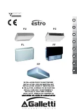
Page 1: ...ZIONE USO E MANUTENZIONE INSTALLATION USE AND MAINTENANCE INSTALLATION USAGE ET MAINTENANCE INSTALLATION GEBRAUCH UND WARTUNG INSTALACIÓN USO Y MANTENIMIENTO INSTALAÇÃO USO E MANUTENÇÃO INSTALLATIE GEBRUIK EN ONDERHOUD FC FL FU FF FP ...

Page 2: ...uno spazio sufficiente a contenere l apparecchio e che ci siano gli spazi necessari per le operazioni di installazione e manutenzione fig spazi rispetto punto 2 2 Non vi siano ostruzioni al passaggio dell aria sia in aspirazione sia in mandata 3 Gli attacchi idraulici abbiano posizione e misure come richiesti dall apparecchio fig 2_FL 2_FU e 2_FC 4 La linea elettrica di alimentazione abbia le cara...

Page 3: ...iledicopertura FL FPedFU possonoessere ruotate di 180 per dirigere il flusso direttamente in ambiente o verso la parete di sostegno della macchina Le griglie e le portelle laterali sono montate ad incastro sul mobile di copertura Prima di procedere al loro smontaggio per orientarle diversamente togliere corrente al ventilconvettore e dotarsi di guanti protettivi 8 MANUTENZIONE ATTENZIONE Le operaz...

Page 4: ... i costi relativi ai ricambi ed alla manodopera necessaria per la riparazione sono a carico del cliente 6 Comespecificatodaiterminidilegge DL199 l obbligodellagaranziaall utilizzatore finale è a carico del venditore la società presso la quale ha effettuato l acquisto Galletti attiverà le procedure di garanzia su richiesta del venditore 7 La garanzia Galletti non copre Controlli manutenzioni ripara...

Page 5: ... who are in a bathtub or shower Remove the cabinet where existing by unscrewing the 4 fastening screws reachable through the lifted side doors figure 3 page 29 In case of FU models unscrew the 2 screws on the front panel Install the unit at distances from the walls shown in Figure 9 Fix the bearing unit to the wall using the 4 mounting slots and the anchor screws suitable for the wall ceiling keep...

Page 6: ...upplied GNYE Yellow Green earth IL Lineswitch notsupplied M Motor RD Red min speed WH White common 1 To command accessory 8 MAINTENANCE WARNING Maintenance must only be carried out by an assistance centre authorised by the manufacturer or by qualified personnel For safety reasons before carrying out any maintenance or cleaning operation switch off the unit turning the selection switch to Stop and ...

Page 7: ...aller 2Contacttheinstaller Units are marked with the following symbol This means that electrical and electronic products may not be mixed with unsorted household waste Do NOT try to dismantle the system yourself the dismantling of the system treatment of the refrigerant of oil and of other parts must be done by an authorized installer and must comply with applicable legislation Units must be treat...

Page 8: ...illage REMARQUE Les versions FLI FCI et FUI sont des variantes équipées d un moteur INVERTER BLDC 4 CARACTERISTIQUES DIMENSIONNELLES figure 2 pages 27 29 5 INSTALLATION ATTENTION Avant d installer le ventilo convecteur s assurer que 1 L espace du lieu d installation est suffisant pour contenir l appareil et qu il y a convenablement de l espace pour les opérations d installation et de maintenance f...

Page 9: ...et conformément aux dispositions de sécurité en vigueur S assurer que la tension du secteur correspond à la valeur indiquée sur la plaque signalétique de l appareil Pour chaque ventilo convecteur prévoir une prise de courant individuelle et un interrupteur avec fusible de protection adéquat BK Noir vitesse 6 BU Bleu vitesse 5 GY Gris vitesse 4 BN Marron vitesse 3 VT Violet vitesse 2 RD Rouge vites...

Page 10: ...OYAGE ATTENTION Le nettoyage du filtre ne doit être effectuées que par un centre d assistance agréée par le fabricant ou par du personnel qualifié Pour des raisons de sécurité avant de procéder à toute opération d entretien ou de nettoyage éteindre l appareil en portant le sélecteur de vitesse sur Arrêt et l interrupteur de la prise de courant sur 0 OFF Nettoyer le filtre à air au moins une fois p...

Page 11: ... Modelle die mit einem INVERTER BLDC Motor ausgerüstet sind 4 ABMESSUNGEN Abbildung 2 Seite 26 28 5 INSTALLATION ACHTUNG Vor der Installation des Ventilatorkonvektors sicherstellen dass 1 der Installationsort ausreichend groß ist um das Gerät aufzunehmen und dass ausreichend Platz zur Verfügung steht um die Installation und die Wartung auszuführen Abb Platzbedarf bez Punkt2 2 der Luftdurchgang Ein...

Page 12: ... ein allpoliger Trennschalter in Überspannungskategorie III zur Verfügung stehen In den Schaltplänen werden die folgenden Abkürzungen benutzt STROMLAUFPLAN MOTOREN MIT 6 GESCHWINDIGKEITEN ABBILDUNG 7 Die gestrichelten Verbindungen müssen vom Installateur hergestellt werden Die Stromanschlüsse müssen in spannungslosem Zustand gemäss den geltenden Vorschriften ausgeführt werden Kontrollieren dass di...

Page 13: ...des Filters darf nur von einem vom Hersteller autorisiertem Kundendienstzentrum oder von qualifiziertem Personal ausgeführt werden Vor jeder Wartungs oder Reinigungsarbeit aus Sicherheitsgründen das Gerät ausschalten indem der Geschwindigkeitsschalter auf Halt und der Hauptschalter auf 0 OFF gestellt wird DenLuftfiltermindestenseinmalmonatlichundvorjederBenutzungssaison reinigen vor der Heizsaison...

Page 14: ...TALACIÓN ATENCIÓN Antes de instalar el ventiloconvector asegúrese de lo siguiente 1 El lugar de instalación debe tener un espacio suficiente para contener el equipo y debe tener los espacios necesarios para las operaciones de instalación y mantenimiento fig espacios requeridos punto 2 2 No debe haber obstrucciones para el paso del aire tanto de aspiración como de impulsión 3 La posición y las medi...

Page 15: ...iamente la tensión de conformidad con lo establecido por las normativas de seguridad vigentes Controlar que la tensión de red corresponda a aquélla indicada en la placa del aparato A cada ventiloconvector se deberá destinar una toma de corriente singular y un interruptor con adecuado fusible de protección BK Negro velocidad 6 BU Azul velocidad 5 GY Gris velocidad 4 BN Marrón velocidad 3 VT Morado ...

Page 16: ...ntro de asistencia autorizado por el fabricante o por personal cualificado Por motivos de seguridad antes de efectuar cualquier operación de mantenimiento o limpieza se deberá apagar el aparato disponiendo el conmutador de velocidad en Parada y el interruptor de línea en 0 OFF Limpiarelfiltrodeairealmenosunavezalmesyantesdecomenzarcadaperíodo deuso antesdecomenzarcadaperíododecalefacciónydeacondic...

Page 17: ...variantes equipadas com motor INVERSOR BLDC 4 DADOS DAS DIMENSÕES figura 2 páginas 27 29 5 INSTALAÇÃO ATENÇÃO Antes de instalar o ventiloconvector certificar se que 1 O local da instalação tenha espaço suficiente para alojar o aparelho e que haja os espaços necessários para as operações de instalação e manutenção fig espaços em referência ao ponto 2 2 Não haja obstruções na passagem do ar em aspir...

Page 18: ...onforme as normativas de segurança em vigor Verifique se a tensão de rede corresponde àquela indicada na placa do aparelho Para cada ventiloconvector prevê uma tomada de corrente individual e um interruptor com um fusível de proteção adequado BK Preto velocidade 6 BU Azul velocidade 5 GY Cinza velocidade 4 BN Marrom velocidade 3 VT Roxo velocidade 2 RD Vermelho velocidade 1 CN Conector tipo fast o...

Page 19: ...ificar as peças internas nunca utilizar solventes químicos agressivos não limpar a grelha de saída do ar com água muito quente 10 PESQUISA DE AVARIAS Se o ventiloconvector não funcionar correctamente antes de pedir a intervenção do serviço de assistência técnica efectuar os controlos indicados na tabela apresentada a seguir Se não conseguir resolver o problema contactar o revendedor ou o centro de...

Page 20: ...lgende controleren 1 De plaats van installatie moet voldoende ruimte hebben om het toestel te zetten en er moet voldoende ruimte zijn voor de werkzaamheden van installatie en onderhoud fig ruimte zie punt 2 2 De luchtpassage mag geen obstructies ondervinden zowel in aanzuiging als in toevoer 3 De hydraulische koppelingen moeten op de plaats zitten en maten hebben zoals door het toestel is vereist ...

Page 21: ...oor die door de installateur moeten worden verricht Verricht de elektrische aansluitingen volgens de toepasselijke veiligheidsvoorschriften na de spanning te hebben gedeactiveerd Controleer of de netspanning overeenstemt met de waarde die is vermeld op het plaatje van het apparaat Elke ventilatorluchtkoeler vereist een apart stopcontact met een geschikte beschermingszekering BK Zwart snelheid 6 BU...

Page 22: ...i de schroeven om de plaatjes te verwijderen en verwijder het filter bij de inbouwversie FC krijgt u toegang tot de ventilatorconvector via het inspectieluikje en verwijder het filter door de bevestigingsbeugels 90 te draaien versieFU verwijderdeluchtfiltersindeafzuigroostersophetvoorpaneelvan de behuizing reinig het filter met lauw water of in geval van droge stof met perslucht plaats het filter ...

Page 23: ...23 FC66000611 07 È severamente vietata la riproduzione anche parziale di questo manuale All copying even partial of this manual is strictly forbidden G H ...

Page 24: ...24 FC66000611 07 È severamente vietata la riproduzione anche parziale di questo manuale All copying even partial of this manual is strictly forbidden H ű ű ...

Page 25: ... berendezést a rendszer szétszerelését a h t folyadékkal az olajjal és más részekkel való m veleteket erre jogosult szakemberrel végeztesse és kövesse az érvényben lév jogszabályokat Az egységeket újrafeldolgozásra újrahasznosításra specializálódott üzemben kell feldolgozni Amennyiben meggy z dik arról hogy a termék hulladékfeldolgozása megfelel en történik segíthet megel zni a környezetre és az e...

Page 26: ...26 FC66000611 07 È severamente vietata la riproduzione anche parziale di questo manuale All copying even partial of this manual is strictly forbidden 1_FL 1_FU 1_FC 1_FF 1_FP ...

Page 27: ...6 208 198 246 95 1194 251 918 48 497 185 259 155 220 195 348 120 478 234 208 271 10 11 1404 251 1128 48 497 185 259 155 220 195 348 120 478 234 208 271 12 1614 251 1338 48 497 185 259 155 220 195 348 120 478 234 208 271 F C A B C D E F G H L M N P Q R S T U V Y 1 4 584 224 498 51 458 163 263 149 198 187 335 99 189 486 208 198 436 464 61 5 6 794 224 708 51 458 163 263 149 198 187 335 99 189 486 208...

Page 28: ... 198 856 884 61 95 1004 249 918 48 497 185 259 155 220 195 348 120 215 478 234 208 856 884 67 10 111214 249 1128 48 497 185 259 155 220 195 348 120 220 478 234 208 1066 1094 67 12 1424 249 1338 48 497 185 259 155 220 195 348 120 220 478 234 208 1276 1304 67 2_FF 2_FP C A 91 308 564 B G N E R 4 4 DF 4 DF 4 F 3 1 2 2 T S 5 D P M F P A B C D E F G M N P R S T 1 4 774 226 498 51 458 163 263 187 335 99...

Page 29: ...00 10 12 3 20 700 1000 3 5 2 1 2_FL F L A B C D E F G H L M N P R 1 4 774 226 498 51 458 163 263 149 198 187 335 99 486 5 6 984 226 708 51 458 163 263 149 198 187 335 99 486 7 9 1194 226 918 51 458 163 263 149 198 187 335 99 486 95 1194 251 918 48 497 185 259 155 220 195 348 120 478 10 11 1404 251 1128 48 497 185 259 155 220 195 348 120 478 12 1614 251 1338 48 497 185 259 155 220 195 348 120 478 4...

Page 30: ...amente vietata la riproduzione anche parziale di questo manuale All copying even partial of this manual is strictly forbidden CN IL N 230V 1 50Hz L 5 6 7 L N 4 M 1 GNYE WH BK BU RD 6 CN IL N 230V 1 50Hz L M 1 GNYE WH BK BU RD ...

Page 31: ...31 FC66000611 07 È severamente vietata la riproduzione anche parziale di questo manuale All copying even partial of this manual is strictly forbidden 7 ...

Page 32: ...32 FC66000611 07 È severamente vietata la riproduzione anche parziale di questo manuale All copying even partial of this manual is strictly forbidden 8_FF 8_FP 8_FC 8_FL 8_FU ...

Page 33: ...07 È severamente vietata la riproduzione anche parziale di questo manuale All copying even partial of this manual is strictly forbidden 9_FU 90 mm 90 mm 140 mm 9_FL 90 mm 100 mm 90 mm 140 mm 9_FC 140 mm 300 mm 300 mm ...

Page 34: ... FC66000611 07 È severamente vietata la riproduzione anche parziale di questo manuale All copying even partial of this manual is strictly forbidden 9_FF 9_FP 140 mm 300 mm 300 mm 90 mm 140 mm 90 mm 100 mm ...

Page 35: ...28 319 Portata acqua Perdita di carico Pressure drop Resa batteria addizionale riscaldam ento Attacchi idraulici Water connections 2 13 2 29 136 137 156 177 187 201 1 55 1 56 1 78 2 02 27 49 52 55 33 39 44 47 50 11 8 8 32 38 44 329 409 429 21 13 13 3 5 2 9 257 307 12 14 17 4 9 4 4 3 7 2 0 1 7 7 9 14 17 20 2 8 2 6 2 2 261 216 8 11 1 58 364 328 298 0 95 1 14 1 30 1 43 167 149 132 0 90 206 8 1 6 6 2 ...

Page 36: ... 60 1 74 1 99 kW kPa kW l h kPa dB A dB A kW Attacchi idraulici Water connections Contenuto acqua Water content Pressione sonora 5 6 5 6 2 l h Resa batteria addizionale riscaldam ento Portata acqua Perdita di carico Pressure drop Portata aria Air flow rate Potenza assorbita Electrical input Num ero ventilatori Num ber of fans 5 5 4 6 3 5 3 2 276 308 401 480 16 12 7 6 30 21 50 52 47 45 26 35 43 48 ...

Page 37: ... 75 3 22 3 39 3 63 1 73 2 37 3 22 3 7 2 8 16 18 6 1 5 8 10 12 5 5 4 8 13 15 4 8 6 3 8 2 9 5 10 0 10 6 4 6 929 876 837 720 556 424 5 8 13 16 18 20 35 43 52 56 57 60 55 52 51 47 38 30 3 21 3 96 4 80 5 34 5 52 5 77 506 484 469 421 347 282 3 87 4 09 4 40 1065 991 938 785 582 427 6 11 18 24 27 30 7 4 6 9 6 6 5 5 4 1 3 0 5 9 14 20 22 25 12 5 11 6 11 0 9 2 6 8 5 1 444 601 808 965 1020 1096 5 8 14 19 21 2...

Page 38: ...a 1 l h ESTRO 1 2 Motore velocità Motor speeds Resa raffreddam ento totale 1 kW 2 67 3 17 3 87 4 77 5 00 5 33 2 98 3 52 4 37 5 40 5 77 6 20 2 93 3 42 4 19 5 26 5 81 6 27 1 96 2 32 2 92 3 65 3 90 4 20 2 08 2 47 664 818 857 914 926 991 1065 503 587 719 902 998 1075 5 7 10 14 16 17 8 11 16 24 27 30 7 9 13 19 23 26 3 6 4 0 4 9 6 0 6 8 7 2 3 6 4 2 5 2 6 5 6 9 7 4 3 7 4 2 5 2 6 6 7 4 8 0 8 12 13 14 7 9 ...

Page 39: ...acqua 1 l h ESTRO 1 2 Motore velocità Motor speeds Resa raffreddam ento totale 1 kW 4 41 5 82 7 38 3 36 3 89 4 66 5 95 4 11 5 31 6 24 7 50 6 98 8 40 8 98 8 02 7 11 17 14 0 11 2 8 6 757 983 1232 15 10 6 47 54 61 56 49 42 non disponibile not available non disponibile not available 2 53 3 05 4 5 5 2 4 6 43 49 5 96 2 75 3 29 4 21 4 95 5 97 6 39 577 706 911 1071 1287 1075 668 800 1022 1199 1440 1541 4 ...

Page 40: ...Azienda certificata UNI EN ISO 9001 e OHSAS 18001 Company UNI EN ISO 9001 and OHSAS 18001 certified ...

Reviews: