25
ESTRO GT
FC66003933-1
FC66003937 - Rev 00
ALL COPYING, EVEN PARTIAL, OF THIS MANUAL IS STRICTLY FORBIDDEN
7
WIRING DIAGRAMS
MYCOMFORT LARGE
Wall-mounted microprocessor control.
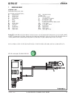
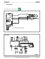
Key to symbols used in wiring diagrams:
Vo
Extra-low speed
V1
Minimum speed
V2
Medium speed
V3
Maximum speed
L
Phase
PE
Ground
N
Neutral
RE
Heating element
SW
Water sensor
SA
Air sensor
SU
Humidity Probe
DI1
Digital 1 input
DI2
Digital 2 input
Each fan-coil requires a switch (IL) on the feeder line with a distance of at least 3 mm between the opening contacts, and a suitable safety fuse (F).
Warning
the EMC filters connected to frequency converters (inverters) can create leakage currents toward ground (in order to make the unit EMC
compliant, by reducing conducted emissions on power supply line). Depending on installation site, this can force the cut out of the differential safety switch.
It is recommended to install a separate differential safety switch, only for the BLDC unit, with an adjustable threshold for the cut out current.
CI12
Digital input common
A/B/GND
RS 485
F
Fuse (not supplied)
IL
Circuit breaker (not supplied)
VC
Solenoid valve - Cooling
VH
Solenoid valve - Heating
.....
Electrical connections to be made by installer
101
0-10V 1 Output
COM
0-10V Output Common
102
0-10V 2 Output
DO2
Digital 2 output
DO1
Digital 1 output
CO12
Digital output Common
ESTRO GT wiring diagram , BRUSHLESS EBM motor

