background image

HIWARM

20

All copying, even partial, of this manual is strictly forbidden

RG66007967 - Rev 02

Double water circuit: 

-  Air conditioning circuit with reversible cooling circuit side and variable set-point between min/max with potential-free 

contact or with 0-10V or 4-20 mA signal.

-  Total heat recovery (for simultaneous cooling) or in any case prioritised DHW circuit. This circuit is separate and does 

not need long heating/cooling stages of inertial storage, like similar products on the market, which jeopardise energy 
efficiency especially during summer operation.

The basic selection when developing the range of multifunction units consists in using the following:
-  Scroll or twin-rotary compressors.
- Brazed plates.
- High-efficiency fans.
-  Electronic expansion valve.
-  AISI 316 Stainless steel high-efficiency plate heat exchangers.
-  Advanced electronic control allows load partialisation requirements to be adequately met.
For optimal partial load operation, which is ever more an object of evaluation and a discriminating factor in the technical 
choice of heating technicians.

The structure of the 

HiWarm

 units has the following characteristics:

Indoor unit:

  side panelling in galvanised sheet metal painted with polyester epoxy powders and polymerised in the oven at 180°C and 

a front cover that incorporates the Display, on two basic levels (LCD) and a 10” Graphic Touch Screen Windows CE. The unit 
is fully panelled but can be accessed on 3 sides since the panels can be easily removed, thereby simplifying maintenance 
and/or inspections. All routine maintenance is performed from the front of the unit. 

Outdoor unit:

  side panelling in galvanised sheet metal painted with polyester powders and polymerised in the oven at 180°C. The unit is 

totally faired and panelled and is available in RAL9002 (Grey White).

  6-pole axial fans with blades having a high degree of overlapping, combined with asynchronous motors with an external 

rotor (or synchronous with permanent magnets) and continuous modulation of the rotation speed.

Remote unit for indoor installation (attic):


  panelling in galvanised sheet metal painted with polyester powders and polymerised in the oven at 180°C. The unit is 

totally faired and is available in RAL9002 (Grey White).

  Radial fans with brushless motors are used, which are ideal for continuous and efficient modulation. Maximum head 

available at 200 Pa.

The components are distributed to guarantee easy access and the layout ensures optimum weight distribution on the unit's 
base.

Summary of Contents for HiWarm Series

Page 1: ...R410A eco 12 kW 22 kW 33 kW MULTIFUNCTION UNIT AIR WATER HEAT PUMP INSTALLATION USE AND MAINTENANCE MANUAL GB...

Page 2: ......

Page 3: ...or optimal use of our product for maximum comfort Please carefully read the recommendations provided in the following pages and place the manual at the disposal of the unit managers and maintenance te...

Page 4: ...HIWARM 4 All copying even partial of this manual is strictly forbidden RG66007967 Rev 02...

Page 5: ...m found in the unit documentation by fax at least one week in advance Should this form not be found please contact GALLETTI Tel 39 051 8908111 Fax 39 051 8908122 e mail assistenza galletti it 4 OUR AP...

Page 6: ...2 3 Operational safety 14 2 2 4 Residual risk areas 14 2 3 LOCATION OF THE SAFETY LABELS 15 2 3 1 Description of the safety labels 15 2 4 GENERAL SAFETY RULES 17 2 4 1 Attention and maintenance 17 2 4...

Page 7: ...D MANAGEMENT FUNCTION 41 6 3 USER INTERFACE 42 6 3 1 Description of the keypad 42 6 3 2 Main screen 43 6 3 3 Selecting the control mode 43 6 3 4 Selecting the set point 46 6 3 5 Alarms 47 6 3 6 Operat...

Page 8: ...bols and their meaning Their purpose is to highlight specific information such as The operating rules described in this manual are an integral part of the unit supply These rules are also intended for...

Page 9: ...e take all the precautions necessary The pressurised fluids in the cooling circuit and the presence of electrical components can cause hazardous situations during installation and maintenance operatio...

Page 10: ...t kg 50 Alimentazione Power supply 230 1 50Hz Potenza assorbita Massima Maximum power input kW 0 4 Corrente massima Full load ampere FLA A 1 66 Corrente di spunto Starting Current LRA A 0 0 10 All cop...

Page 11: ...erstood the user instructions well together with the meaning of any symbols on the unit Potential accidents can be prevented by following these technical instructions with reference to the Machinery D...

Page 12: ...he Standards in force Apply a WORKS IN PROGRESS sign on all sides of the unit Carefully check the unit according to the list of operations specified in this manual The unit must only be used by qualif...

Page 13: ...ith the unit off and the power supply disconnected Once the unit is cleaned the operator must make sure there are no worn or damaged parts or others that are not fastened securely otherwise a maintena...

Page 14: ...arts are used has a component that is either modified or replaced without written authorisation from the MANUFACTURER especially when the efficiency of the safety systems is intentionally reduced or e...

Page 15: ...e functions of the unit and the consequent risks b Read the use and maintenance manual carefully before operating the unit Power supply label a Do not use water to extinguish fire b Do not smoke and o...

Page 16: ...l copying even partial of this manual is strictly forbidden RG66007967 Rev 02 a Electric voltage hazard b Risk of shearing in the finned coil area c Risk of burns Liquid refrigerant Hazard moving mech...

Page 17: ...check that the safety devices are in perfect working condition Make sure that no unqualified or unauthorised persons enter the unit area Verify that the fire extinguisher is in place Periodically veri...

Page 18: ...solvents must be used even if weak as they damage the paint and increase the formation of rust If a jet of water penetrates the electrical equipment the contacts oxidise and the unit can malfunction T...

Page 19: ...oned at a height with simple brackets Outdoor unit for indoor use ductable compact with backward curved blade fans activated by an EC synchronous permanent magnets motor designed for attics Expansion...

Page 20: ...or unit side panelling in galvanised sheet metal painted with polyester epoxy powders and polymerised in the oven at 180 C and a front cover that incorporates the Display on two basic levels LCD and a...

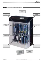
Page 21: ...manual is strictly forbidden RG66007967 Rev 02 3 2 MAIN COMPONENTS OF THE INDOOR UNIT PLATE HEAT EXCHANGERS DISPLAY INVERTER SOLENOID VALVES LIQUID SEPARATOR COMPRESSOR CYCLE INVERSION VALVE LIQUID RE...

Page 22: ...well as the need to minimise the amount of oil entrained into the transients and is a parameter that cannot be modified INTERNALTEMPERATURE C M O D E L W I T H I N V E R T E R STANDARDMODEL TIME Scro...

Page 23: ...at of R407C units of the same size 20 operating energy supplied by renewable photovoltaic panels 100 useable kW 80 energy absorbed from the environment renewable clean energy TEWI Total Equivalent War...

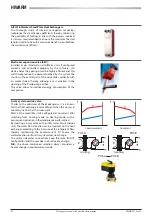
Page 24: ...same IN OUT configuration and the user does not notice any change N B the above mentioned selection always considers a heat exchange in countercurrent mode Countercurrent Cocurrent Electronic expansio...

Page 25: ...n consists of an electrical current being applied to a coil that creates a magnetic field This is transformed into mechanical energy which opens or closes the valve The principle of operation is very...

Page 26: ...ency TheBLDCdoesnotrequireinductioninthestatorwindings there already is a permanent magnet in the rotor There are no relative losses The BLDC has no rotor currents due to the stator induction of the a...

Page 27: ...ber of 25 x 21 65 mm expanded pipes 8 mm diameter in an automatic and controlled process in 0 10 mm thick aluminium fins Expansion is a fey factor and important process as it determines the pipe fin c...

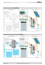
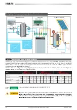
Page 28: ...ng and cooling requirements throughout the year with no fossil fuels Three models can be chosen from classified according to the maximum cooling capacity they can produce Priority production of domest...

Page 29: ...r Domestic hot water Water mains Water mains Storage tank Storage tank Storage tank Storage tank Fan coil Fan coil Flooring Flooring REMOTE UNIT REMOTE UNIT DOMESTIC HOT WATER DOMESTIC HOT WATER HOME...

Page 30: ...the pipes to use to connect the indoor and the outdoor units according to the different sizes of the HiWarm and the length of the line Model 012 022 033 Refrigerant R410A Pipe length m 0 5 6 10 11 15...

Page 31: ...icting the availability of oxygen Once evacuated the area must be ventilated with fans or blowers in order to circulate the air at floor level FLAMMABILITY according to the 34 ASHRAE Standard R 410A i...

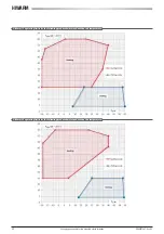
Page 32: ...l of this manual is strictly forbidden RG66007967 Rev 02 HiWarm 12 operating limits for the following produced water and outdoor air temperature HiWarm 22 operating limits for the following produced w...

Page 33: ...ure differential of 8 C lower flow rates could cause excessively low evaporation temperatures which could trigger the safety devices and stop the unit or cause incorrect distribution and risk of heat...

Page 34: ...ign of damage Commissioning report wiring diagram warranty certificate and list of service centres check the integrity of the documents accompanying the unit and of this manual While the unit is being...

Page 35: ...ol on the water side allows the correct functionality of the expansion tank to be verified and any water leaks in the system to be detected in advance sumps on inlet and outlet piping for temperature...

Page 36: ...useful head of the hydraulic pumps in cooling conditions water 12 7 C and air 35 C Inverter driven pumps can run within the limited range over the characteristic range of the pump 012 Absorbed power...

Page 37: ...37 All copying even partial of this manual is strictly forbidden RG66007967 Rev 02 022 Absorbed power kW 0 3 Absorbed current A 1 3 033 Absorbed power kW 0 3 Absorbed current A 1 3...

Page 38: ...it Lastly it is possible to find the minimum recommended protection For the correct sizing of the cable it is necessary to take into account standard reference IEC EN60204 1 1 The selected upstream pr...

Page 39: ...the internal and external unit for a maximum distance of 30m When connecting units with EC fans the power and signal cables must be separate and sized as indicated in the table The 0 10V signal cable...

Page 40: ...can be set downloading all the data records from a web browser or via FTP editing the main parameters in case of an alarm sending an e mail to 5 different recipients GWeb also allows for monitoring to...

Page 41: ...ds and the branch point of the power supply for the power factor correction panel the installed CT must measure all the absorbed currents of the system inductive motors or similar as well as capacitiv...

Page 42: ...ress the PRG key to enter the main menu ESC Press the ESC key to move up one level in the menu UP Press the UP key to go to the next screen or increase the value of a parameter ENTER PresstheENTERkeyt...

Page 43: ...er the main menu use the UP and DOWN keys to scroll the menu to select USER press ENTER and enter the password default 100 using the UP and DOWN keys press ENTER to confirm the password and access the...

Page 44: ...nication board is installed pCOWeb or RS485 that acts as an interface between the main unit control and the supervision system The type of protocol and main communication configuration parameters can...

Page 45: ...hours Band 3 F3 the unit is always on Band 4 F4 the unit is always off Weekly program configuration Once the On Off bands are set they must be used to define the logic of the different days of the wee...

Page 46: ...screen Time band set point solely for the utility A time band for each day of the week can be set from the SET POINT menu to control the variation of the set point during the intervals of the day when...

Page 47: ...lights up Press the ALARM key once to access the list of active alarms then use the UP and DOWN keys to scroll the list Each alarm is identified by a code and a brief description the complete list is...

Page 48: ...ALARM 013 LOW PRESSURE ALARM 015 PRESSURE SWITCH OR COMPRESSOR CIRCUIT BREAKER HIGH PRESSURE ALARM 017 LOW PRESSURE PROBE ALARM 019 HIGH PRESSURE PROBE ALARM 023 FAN CIRCUIT BREAKER ALARM 025 PUMP 1 E...

Page 49: ...VE BOARD ALARM With Frecon APY inverter heat sink over temperature overcurrent during acceleration overcurrent overcurrent during deceleration DC Bus undervoltage DC Bus overvoltage faulty PFC convert...

Page 50: ...unit Faulty high pressure Insufficient air flow rate to the condenser Check that all fans turn correctly Check the condenser air inlet T and prevent any recirculation Check that the maximum RMS voltag...

Page 51: ...the filter must not exceed 2 C saturation temperature Should it happen replace the filters Low condensation T Make sure the condensation control works properly if present Low refrigerant charge Check...

Page 52: ...rs that are too high This leads to regular and continuous system operation and therefore better thermal performance The water heated by the unit is stored inside the tank and the energy stored this wa...

Page 53: ...4 41 6 34 3 46 6 80 3 47 UTILITYWater Flow Rate kg h 714 2696 1458 4834 1472 7565 UTILITYWater Pressure Drops kPa 3 0 37 0 4 0 49 0 11 1 44 0 DISSIPATIONWater Flow Rate m3 h 3500 7000 5250 10500 7000...

Page 54: ...0 30 0 45 0 45 0 60 0 60 Fan Absorbed Current A 1 40 1 40 0 80 0 80 1 10 1 10 COP 3 48 4 03 3 69 3 65 3 91 3 71 UTILITYWater Flow Rate kg h 527 2093 1050 4034 1687 6147 UTILITYWater Pressure Drops kPa...

Page 55: ...atetheworkcarriedoutinthewastecollection disposalandrecyclingfacilitiesandminimisetheenvironmental impact of such processes The law EC 2037 00 that regulates the use of stratospheric ozone depleting s...

Page 56: ...not smoke SPECIAL PROTECTION SYSTEMS FOR THE FIRST AIDERS Wear breathing apparatus and protective clothing MEASURES IN CASE OF ACCIDENTAL DISPERSION PERSONAL PRECAUTIONS Avoid contact with your skin e...

Page 57: ...ic components the product can cause the following due to vapour accumulation and or inhalation of large quantities Loss of consciousness and cardiac disorders aggravated by stress and lack of oxygen L...

Page 58: ...ackaging group Classification code 2A Labels 2 2 ADN ADNR Substance identification number 3163 Hazard identification number 20 Class 2 Number and letter 2nd A Labels 2 IMDG ONU No IMDG 3163 Class 2 2...

Page 59: ...59 All copying even partial of this manual is strictly forbidden RG66007967 Rev 02 NOTES...

Page 60: ...www galletti it 40010 Bentivoglio BO Via Romagnoli 12 a Tel 051 8908111 Fax 051 8908122 Company UNI EN ISO 9001 and OHSAS 18001 certified...

Reviews: