
15
SY66000058 - 0
3
MS
MS
MS
MS
MS
È severamente vietata la riproduzione anche parziale di questo manuale / All copying, even partial, of this manual is strictly forbidden
4.11
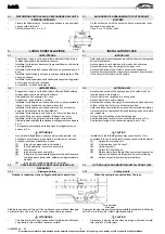
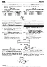
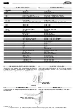
ELECTRIC PARTS COVER
4.12
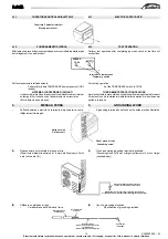
TEST OPERATION
Perform test operation after completing gas leak check at the flare nut
connections.
For cooling operation
-
Set the TEMPORARY switch to COOL.
THREE -MINUTE PROTECTION FEATURE
A protection feature prevents the air conditioner from being activated for about
3 minutes when it is restarted immediately after operation or when the power
switch is turned on.
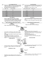
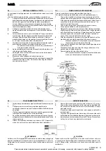
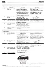
5.
GROUNDING WORK
-
A grounding terminal can be found on the outdoor unit as illustrated.
(1)
When an existing grounding terminal is available.
(Grounding wire of
φ
1.6 mm or larger (solid wire) or 2 mm
2
or larger
(stranded wire))
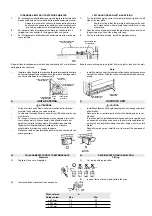
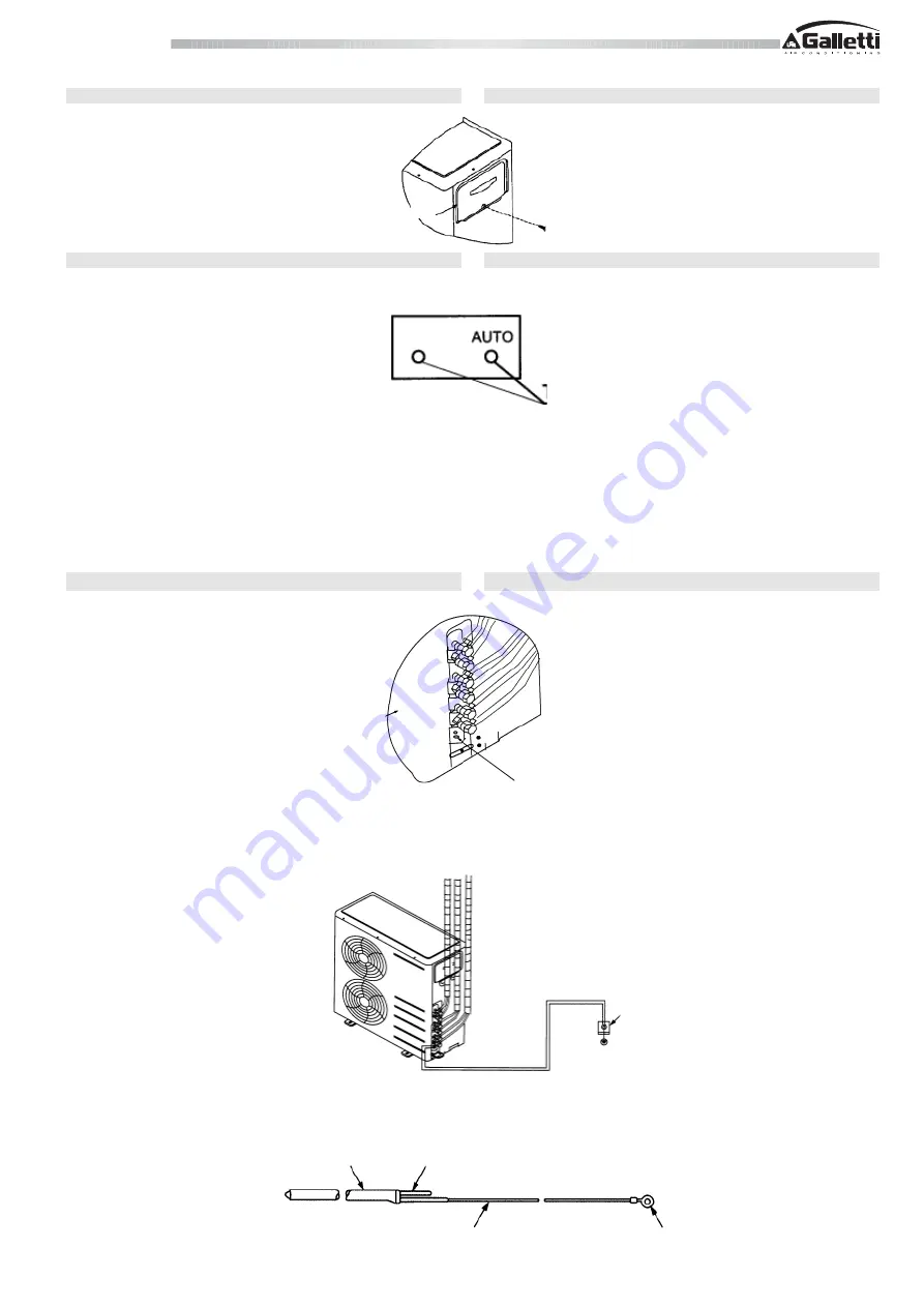
(2)
Use of a grounding electrode.
-
Specification of grounding electrode.
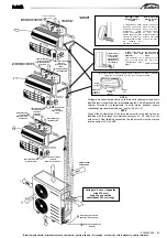
4.11
COPERTURA PARTICOLARI ELETTRICI
4.12
FUNZIONAMENTO DI PROVA
Effettuare una prova di funzionamento dopo aver controllato le perdite di gas
dai collegamenti con dadi svasati.
Per funzionamento in raffreddamento
-
Portare l'interruttore TEMPORARY (temporaneo) su COOL
(freddo)
SISTEMA DI PROTEZIONE DI 3 MINUTI
Un sistema di protezione impedisce al condizionatore di avviarsi per
un tempo di 3 minuti dopo che l'apparecchio viene riavviato o
l'interruttore viene posto su on.
5.
MESSA A TERRA
-
Sull'unità esterna è previsto un terminale di messa a terra, come
raffigurato sull'immagine.
(1)
Quando esiste un terminale di messa a terra.
(Filo di terra di diametro minimo di
φ
1,6 mm o più (filo pieno) o 2 mm²
o più (cavo a più fili)).
(2)
Utilizzare un elettrodo di terra.
-
Caratteristiche dell'elettrodo di terra.
Copertura Particolari elettrici
Electric parts cover
FREDDO
COOL
Interruttore temporaneo
Temporary switch
Vite di presa di terra
Grounding screw
Unità esterna
Outdoor unit
Usarlo esclusivamente per la messa a terra.
Terminal used exclusively for grounding.
Resistenza di terra: meno di 4 ohm (elettrodo di terra esistente)
Grounding resistance: less than 4 ohms (existing grounding electrode)
Plastica al carbonio
Carbon plastic
Nucleo di acciaio
Steel core
filo isolato con PVC
(2 mm2 x3.5m), verde o giallo / verde
pvc-insulated wire
(2 mm2 x3.5m), green or yellow / green
morsetto, M4
terminal, M4


