
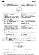
3.5
ELECTRICAL WORK
1.
Prepare the power source for exclusive with the air conditioner. The
supply voltage must be the same as the rated voltage of the air
conditioner.
2.
Do not extend the power cable code by cutting.
Cross section area, mm
2
Rated current
A
>3~6
0.75
>6~10
1
>10~16
1.5
>16~25
2.5
>25~32
4
>32~40
6
>40~63
10
CAUTION
-
Perform the wiring with sufficient capacity. Installation places legally
require a short circuit isolator to be attached to prevent electrical
shock.
For details, consult your nearest electric power company or dealer.
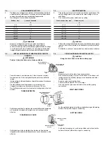
3.6
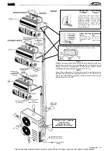
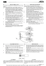
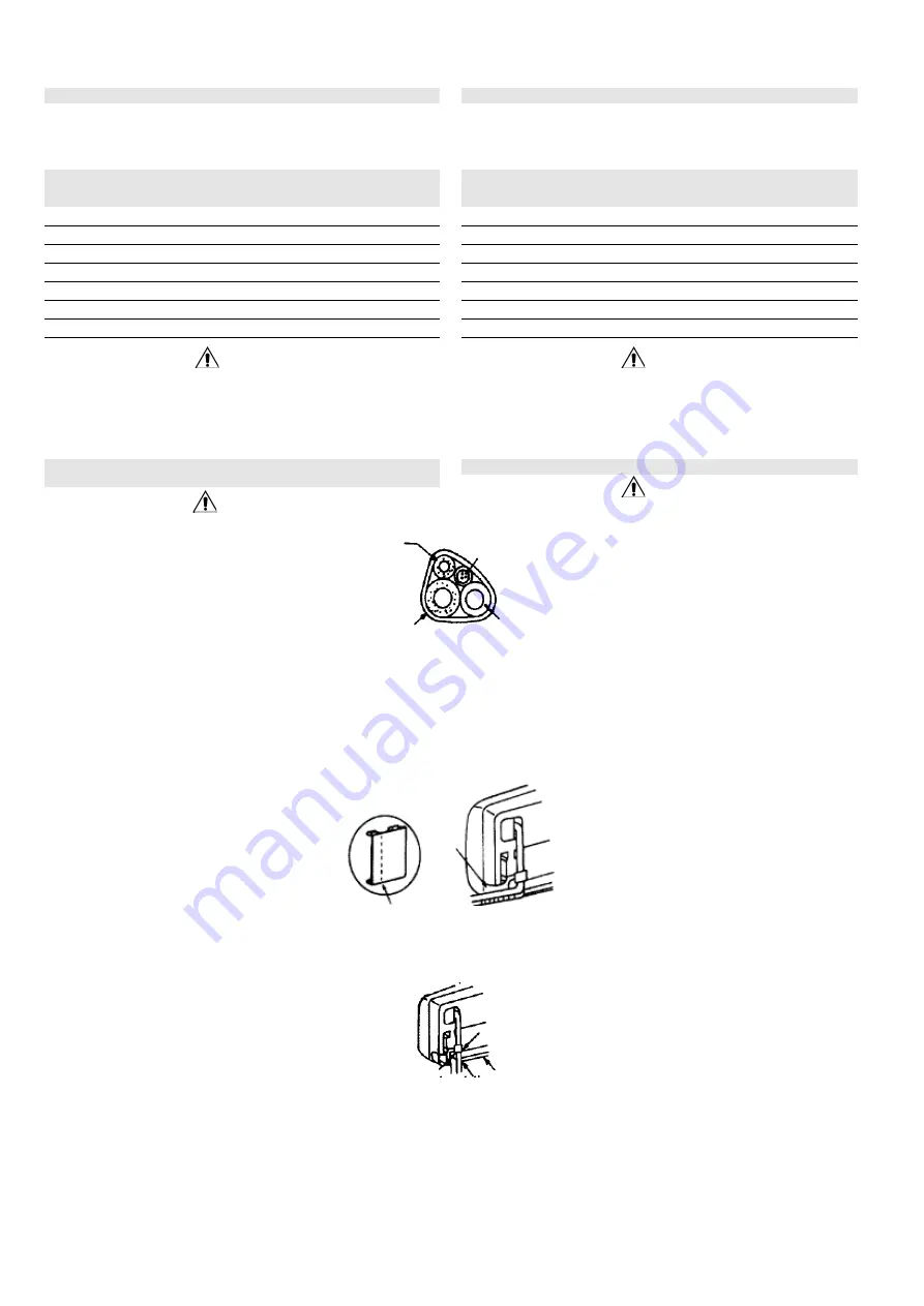
PIPING AND DRAIN HOSE INSTALLATION
CAUTION
Bring the drain hose under the auxiliary pipe.
-
Be careful not to let the drain hose become slack.
-
Do not allow the piping to jut out from the back of the indoor unit.
-
Insulate both of the auxiliary pipings, or condensation and other
troubles may occur.
-
Exercise care in bending the pipes.
-
The curve radius must be 100 mm or larger.
-
Do not reuse the nylon caps installed on the auxiliary piping
connections.
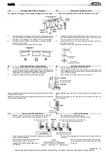
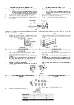
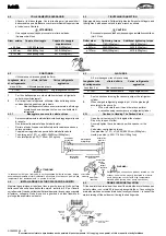
RIGHT-HAND PIPING
-
For the right-hand piping, cut out the rear plate bushing and the piping
holder at a slit with a nipper or something.
BOTTOM PIPING.
-
For the bottom piping, cut out the pipe holder and slit part on the
bottom of the rear plate with a nipper or something.
3.5
COLLEGAMENTI ELETTRICI
1.
Predisporre un collegamento elettrico di alimentazione destinato
unicamente al condizionatore. La tensione di alimentazione deve
corrispondere alla tensione nominale dell'apparecchio.
2.
Non allungare il cavo elettrico tagliandolo.
Sezione, mm²
Corrente nominale
A
>3~6
0.75
>6~10
1
>10~16
1.5
>16~25
2.5
>25~32
4
>32~40
6
>40~63
10
ATTENZIONE
-
Eseguire i collegamenti elettrici con potenza sufficiente.
Per evitare scosse elettriche predisporre un sezionatore
conformemente a quanto previsto dalle regolamentazioni del luogo
in cui l'apparecchio viene installato. Per informazioni dettagliate,
rivolgersi al gestore della rete elettrica o al distributore di zona.
3.6
INSTALLAZIONE DELLE TUBAZIONI E DEL TUBO DI
SCARICO
ATTENZIONE
·
Portare il tubo di scarico sotto il tubo ausiliario.
-
Fare attenzione a non lasciare che il tubo di scarico si allenti.
-
Non lasciare che il tubo sporga dalla parte posteriore dell'unità
interna.
-
Isolare entrambi i tubi ausiliari per evitare la formazione di condensa
o altri problemi.
-
Prestare attenzione nell'operazione di curvatura dei tubi.
-
Il raggio di curvatura non deve essere inferiore a 100 mm.
-
Non riutilizzare i cappucci di nylon montati sulle giunzioni dei tubi
ausiliari.
TUBAZIONE DESTRA
-
Sulla tubazione di destra, tagliare la boccola della piastra posteriore
ed il porta-tubo formando un intaglio con un tronchese o altro
attrezzo.
TUBAZIONE SUL FONDO
-
Sulla tubazione di fondo, tagliare il porta-tubo ed il particolare
intagliato sul fondo della piastra posteriore con un tronchese o altro
attrezzo
Tubo di collegamento
Connective piping
Nastro
Tape
Cavo di collegamento
Connective cable
Tubo di scarico
Drain hose
Boccola piastra posteriore
Rear plate bushing
Particolare con
intaglio
Slit part
Particolare con intaglio
Slit part
Particolare con
intaglio
Slit part
Particolare con intaglio
Rear plate
Piastra posteriore
Rear plate


