MPED
36
1
2
3
4
5
T>35°C
All copying, even partial, of this manual is strictly forbidden
RG66012163 - Rev 00
12.2
DE-SUPERHEATER FOR PARTIAL HEAT RECOVERY
The partial heat recovery option is provided by a braze-welded plate heat exchanger placed in
series on the compressor delivery (typically in series in relation to the finned pack condenser)� Its size is designed to limit pressure drops on the
refrigerant side to a minimum�
All machines configured with heat recovery use as per standard modulating condensation control� In order to
avoid any unbalance in the cooling circuit, if there are start-ups with very low water temperatures at recovery (<35°C), the hydraulic recovery circuit
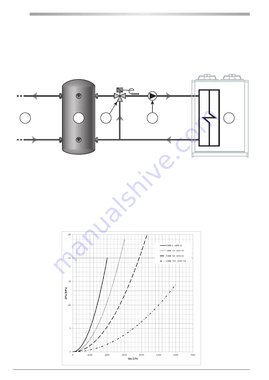
must be set up as indicated in the following figure: a low water temperature at recovery would cause a drop in the condensation temperature and
therefore an insufficient pressure jump on the expansion valve with the ensuing risk of the safety devices being triggered�
1
Utility side
2
Storage tank
3
Mixing valve
4
Circulation pump
5
On-board de-superheater
The bulb of the 3-way mixer valve is placed at the de-superheater exchanger inlet� By mixing the hot water produced by the recovery with colder water
from the tank, it reduces the time needed for the system to reach full operating capacity to a few moments�
A buffer tank must be placed between the unit and the utility since the demand for hot water and its availability are not simultaneous, because it needs the
compressors to be running�
It should be pointed out that the heat recovery output is linked to the dispensed cooling output and that, therefore, in partial load situations it is also
reduced just the same; this aspect must be taken into consideration for the dimensions of the buffer tank�
The partial heat recovery option is supplied only with the de-superheater exchanger� The other components of the circuit laid out in the previous figure are
not included in the supply�


