5
UT66001122 - rev. 01
RE
È severamente vietata la riproduzione anche parziale di questo manuale / All copying, even partial, of this manual is strictly forbidden
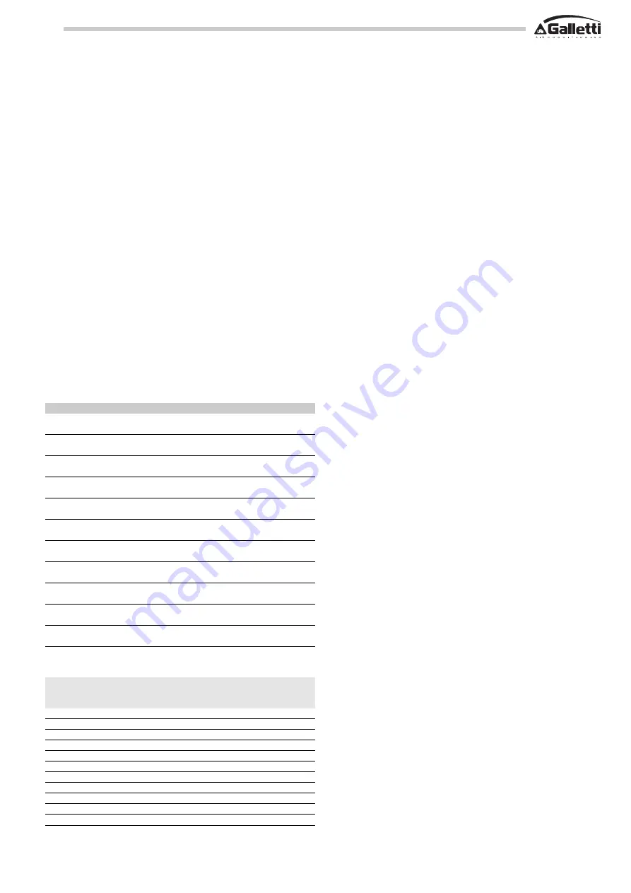
Code
Name
Description
UYRE06M2
RE06M2
Single-phase
electric heating element module,
safety devices, power relays, models
UTN 06, 08
UYRE12T3
RE12T3
Three-phase
electric heating element module,
safety devices, power relays, model
UTN 12
UYRE12T6
RE12T6
Three-phase
electric heating element module,
safety devices, power relays, model
UTN 12
UYRE16T4
RE16T4
Three-phase
electric heating element module,
safety devices, power relays, model
UTN 16
UYRE16T9
RE16T9
Three-phase
electric heating element module,
safety devices, power relays, model
UTN 16
UYRE22T4
RE22T4
Three-phase
electric heating element module,
safety devices, power relays, model
UTN 22
UYRE22T9
RE22T9
Three-phase
electric heating element module,
safety devices, power relays, model
UTN 22
UYRE30T9
RE30T9
Three-phase
electric heating element module,
safety devices, power relays, model
UTN 30
UYRE30T12
RE30T12 Three-phase
electric heating element module,
safety devices, power relays, model
UTN 30
UYRE40T9
RE40T9
Three-phase
electric heating element module,
safety devices, power relays, model
UTN 40
UYRE40T12
RE40T12 Three-phase
electric heating element module,
safety devices, power relays, model
UTN 40
Therefore, avoid:
- positions directly exposed to sunlight;
- positions exposed to direct currents of warm or cold air;
- placing obstacles that impede an accurate temperature reading
(drapes or furniture);
- constant presence of steam
- covering the panel or building it into the wall.
The minimum gauges of the power cables will depend on the
electrical inputs specified in table 1, in compliance with current
regulations.
To guarantee the efficiency of a thermal ventilating unit fitted with
a supplementary RE heating element module, comply with the
following directions:
- keep the air filter clean;
- do not pour liquids inside the equipment;
- make absolutely sure you do not obstruct the air outlet or inlet
of the thermal ventilating unit;
Make the electrical connections as shown in figures 5 and 6:
5) RE + TSA (automatic safety thermostat) + TSM (manual safety
thermostat) - (single-phase 230V 1 50Hz)
6) RE + TSA (automatic safety thermostat) + TSM (manual safety
thermostat) - (three-phase 400V 3 +N 50Hz)
In the wiring diagrams the following abbreviations are used:
- K1
Contactor
- R1,R2,R3
Heaters
- TSA
Automatic safety thermostat
- TSM
Manual safety thermostat
HOW TO ORDER
OPERATING LIMITS
Model
Minimum air Power
Code
flow rate
(W)
(m
3
/h)
UTN 6-8
400
2000
UYRE06M2
UTN 12
800
3000
UYRE12T3
UTN 12
1100
6000
UYRE12T6
UTN 16
1000
4500
UYRE16T4
UTN 16
1600
9000
UYRE16T9
UTN 22
1000
4500
UYRE22T4
UTN 22
1700
9000
UYRE22T9
UTN 30
2000
9000
UYRE30T9
UTN 30
2500
12000
UYRE30T12
UTN 40
2000
9000
UYRE40T9
UTN 40
2500
12000
UYRE40T12


