19
UT66000806 - 02
UTN
All copying, even partial, of this manual is strictly forbidden
10.6
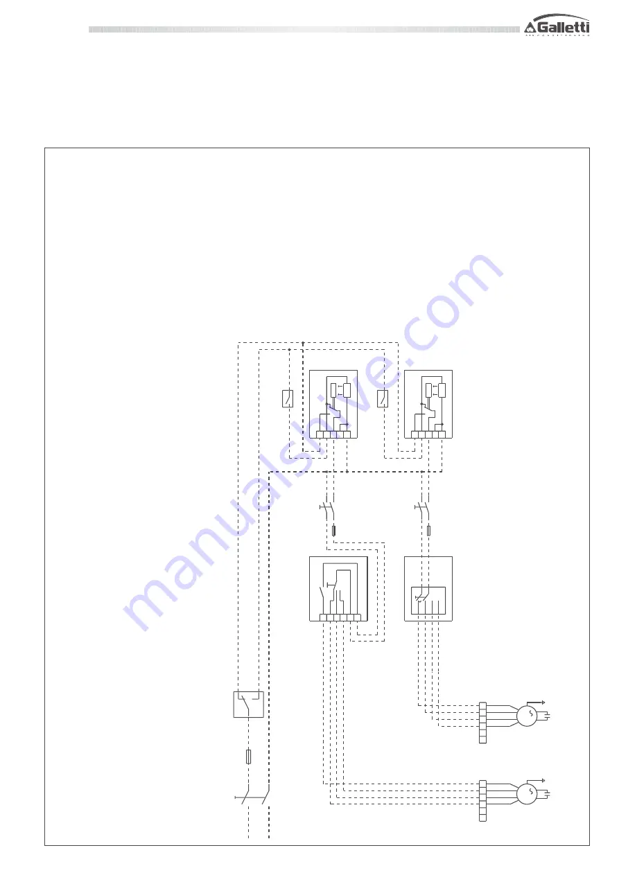
UTN
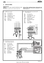
units with
TA
room thermostat with centralised mode selector
and
CD
,
CDE
speed selectors:
BK
=
black, high speed
BU
=
blue, medium speed
CD
=
flush remote speed selection switch
CDE
=
remote speed selection switch
CN
=
faston connector
F
=
protection fuse, not supplied
GNYE
=
green/yellow, ground
GY
=
grey, medium speed
IL
=
mains switch, not supplied
M
=
fan motor
RD
=
red, low speed
SF
=
Centralised mode selector, not supplied
TA
=
room thermostat
TC
=
fan stop thermostat
WH
=
white, common
L
IL
F
N
98
76
54
M 1
SF
CN
RD
BU/GY
BK
WH
9
87
6
5
4
M
1
CN
RD
BU/GY
BK
WH
1
2
3
4
5
6
S
C
CDE
3
2
1
4
RL
S
C
CD
N
N
1
2
3
RF
TA
TC
TC
N
N
1
2
3
RF
TA
IL
IL
F
F
T
T
230 / 1 / 50
10
WIRING DIAGRAMS
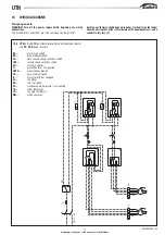
Wiring diagram notes
WARNING! Turn off the power supply before beginning any wiring
connections.
The dashed lines connections must be carried out by the installer.
Each fan-coil thermal-ventilating unit requires a switch (IL) on the feeder
line with a distance of at least 3 mm between the opening contacts, and a
suitable safety fuse (F).

