20
UT66000806 - 02
UTN
All copying, even partial, of this manual is strictly forbidden
RD
BU/GY
BK
WH
6
5
N
4
3
2
1
ACC
S
9 8 7 6 5 4
230 / 1 / 50
M
1
GNYE
L
N
F
SF
T
IL
C
TC
TD
CN
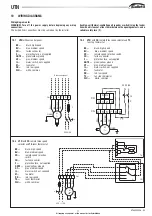
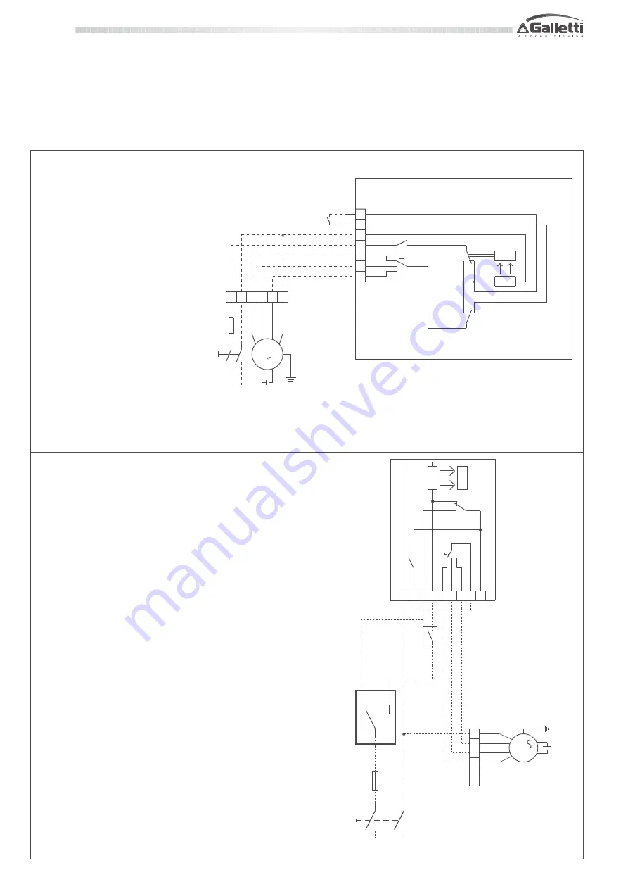
10.7 UTN
units with
TD
wall mounted control
with speed selector, electromechanical
thermostat and summer winter selector:
BK
=
black, high speed
BU
=
blue, medium speed
CN
=
faston connector
F
=
protection fuse, not supplied
GNYE
=
green/yellow, ground
GY
=
grey, medium speed
IL
=
mains switch, not supplied
M
=
fan motor
RD
=
red, low speed
SF
=
centralised mode selector, not
supplied
TD
=
wall mounted control with
speed selector,
electromechanical thermostat
and summer winter selector
WH
=
white, common
L
IL
F
N
N
5
6
1
3
4
2
9
10
S
C
987654
CN
M
1
WH
BK
BU/GY
RD
230 / 1 / 50
TC
SF
ACC
T
TDC
GNYE
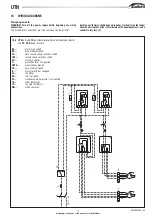
10.8 UTN
units with
TDC
wall mounted control with speed
selector and electromechanical thermostat:
BK
=
black, high speed
BU
=
blue, medium speed
CN
=
faston connector
F
=
protection fuse, not supplied
GNYE
=
green/yellow, ground
GY
=
grey, medium speed
IL
=
mains switch, not supplied
M
=
fan motor
RD
=
red, low speed
SF
=
centralised mode selector, not supplied
TC
=
fan stop motor
TDC
=
wall mounted control with speed selector and
electromechanical thermostat
WH
=
white, common
10
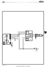
WIRING DIAGRAMS
Wiring diagram notes
WARNING! Turn off the power supply before beginning any wiring
connections.
The dashed lines connections must be carried out by the installer.
Each fan-coil thermal-ventilating unit requires a switch (IL) on the feeder
line with a distance of at least 3 mm between the opening contacts, and a
suitable safety fuse (F).

