22
UT66000806 - 02
UTN
All copying, even partial, of this manual is strictly forbidden
C
V1
V2
V3
1
2
3
4
C
V3
V2
V1
28
27
26
25
L
L
N
N
14
15
16
17
MICROD
V3
V2
V1
L
N
N
PE
L
N
230/1/50
M
1
8
7
6
5
4
9
CN
IPM
SA
SW
RD
BU/GY
BK
WH
IL
F
1
0
.
1
0U
T
N
uni
ts wi
th
M
I
C
R
O
-
D
mi
croprocessor
remot
e
cont
rol
panel
,
for
the automati
c contr
ol
of
the f
an-coi
l:
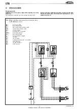
B
K
=
bl
ack,
hi
gh
speed
B
U
=
bl
ue,
medi
um
speed
C
N
=
fast
on
connect
or
F
=
prot
ect
ion f
use,
not
suppl
ied
G
N
Y
E
=
gr
een/
yel
low,
gr
ound
G
Y
=
gr
ey,
medi
um
speed
I
L
=
mai
ns
swi
tch,
not
suppl
ied
I
P
M
=
power
i
nt
er
face
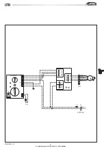
M
=
fan
mot
or
M
I
C
R
O
-
D
=
mi
croprocesor
remot
e
cont
rol
panel
,
for
the
aut
omat
ic
contr
ol
of
the f
an-coi
l
R
D
=
red,
l
ow
speed
S
A
=
Room
t
emperat
ure
probe
for
aut
omat
ic
fan
speed
sel
ect
ion
S
W
=
Wat
er
t
emper
at
ur
e
pr
obe
(opt
ion
for
t
he
MI
CROPROD
cont
rol
),
for
the aut
omat
ic cool
ing/heat
ing mode sel
ect
ion.
W
H
=
whi
te
,
common
1
0W
I
R
I
N
G
D
I
A
G
R
A
M
S
Wi
ri
ng
di
agr
am
not
es
W
A
R
N
I
N
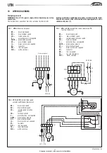
G!
Turn
of
f
the
power
suppl
y
bef
ore
begi
nni
ng
any
wi
ri
ng
connect
ions.
The dashed l
ines connect
ions must
be carr
ied out
by t
he i
nst
al
ler.
Each
fan-coi
l
thermal
-venti
lati
ng
uni
t
requi
res
a
swi
tch
(IL)
on
the
feede
li
ne
wi
th
a
di
st
ance
of
at
l
east
3
mm
bet
ween
the
openi
ng
cont
ac
s
and
a
sui
tabl
e
safety
fuse
(F).

