background image

2

4

UT66000806 

 -


02

U

T

N

Al

l copyi

ng, 

even parti

al

, of 

thi

s manual

 is 

stri

ctl

y f

orbi

dden

1

1M

O

T

O

R

S


E

L

E

C

T

R

I

C

A

L


D

A

T

A

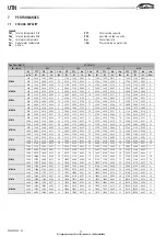
The f

ol

lowi

ng t

abl

e descri

bes t

he characteri

sti

cs of 

the motors at 

avai

labl

e

wor

ki

ng 

condi

ti

ons.

L

e

g

e

n

d

:V

r

Oper

at

ion 

speedXC

P

A

S

S

Power

 i

nput

I

A

S

S

Oper

at

ion 

cur

rent

1

2A

C

C

E

S

S

O

R

I

E

S

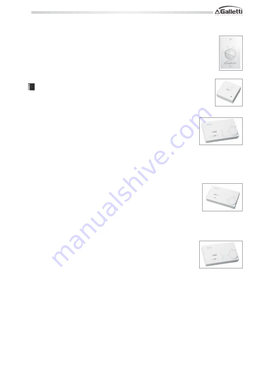
CD 

Fl

ush 

wal

l-

mount

ed 

speed 

sel

ect

or

Fl

ush 

wal

l-mount

ed 

cont

rol

 panel

 i

provi

ded 

wi

th 

4

posi

ti

ons 

(3speed 

st

op) 

rot

at

ion 

sel

ect

or.

The 

CD 

cont

rol

 panel

 al

lows 

the 

ON/

OFF 

and 

fan 

speed

sel

ecti

on of 

the hi

gh pressure f

an coi

l uni

t.

CDE 

wal

mount

ed 

speed 

sel

ect

or

Wal

mount

ed 

cont

rol

 panel

 i

provi

ded 

wi

th 

3

posi

ti

ons 

(3 

speed 

and 

swi

tch 

ON/

OFF 

.

The 

CDE 

cont

rol

 panel

 al

lows 

the 

ON/

OFF 

and 

fan

speed sel

ecti

on of 

the hi

gh pressure f

an co

l uni

t.

TD 

Wal

mount

ed 

cont

rol

 wi

th 

speed

sel

ect

or, 

ther

most

at

 and 

summer-wi

nt

er

sel

ect

or

Wal

mount

ed 

cont

rol

 panel

 compl

et

wi

th

fan 

speed 

sel

ect

or, 

el

ect

romechani

cal

thermost

at

 and 

cool

ing 

heat

ing 

mode

sel

ect

or.Fan speed contr

ol

regul

at

ion 

of

 t

he 

room 

temperat

ure 

and 

coo

ing 

he

ng

mode 

sel

ect

ion:

-  

manual

 sett

ing of 

the f

an speed;

 room 

temperat

ure 

regul

at

ion 

bot

in 

cool

ing 

heat

ing 

mode,


by 

means

of 

fan st

art /

 stop, 

at 

a manual

ly set 

temperature.

TDC 

Wal

mount

ed 

cont

rol

 wi

th 

speed

sel

ect

or 

and 

thermost

at

Wal

mount

ed 

cont

rol

 panel

 compl

et

wi

th 

fan

speed 

sel

ect

or, 

el

ect

romechani

cal

 t

herm

o

s

t

a

t

and 

cool

ing 

heat

ing 

mode 

sel

ect

or.

Fan 

speed 

cont

rol

regul

at

ion 

of 

the 

room

temperat

ure 

and 

cool

ing 

heat

ing 

mode 

sel

ect

ion:

- manual

 set

ti

ng of 

the f

an speed;

room 

temperat

ure 

regul

at

ion 

bot

in 

cool

ing 

heat

ing 

mode,

 by 

mean

fan 

st

art/st

op, 

at

 a manual

ly set

 temperat

ure.

TD4T 

Wal

mount

ed 

cont

rol

 wi

th

speed 

sel

ect

or, 

ther

most

at

 and

s

u

m

m

e

r-wi

nt

er 

sel

ect

or, 

for 

2/4 

pi

pe

syst

em 

wi

th 

val

ves

Wal

mount

ed 

cont

rol

 panel

 provi

ded 

wi

th

fan 

speed 

sel

ect

or, 

el

ect

romechani

cal

thermost

at

and 

cool

ing 

heat

ing 

mode

selector; 

if i

nstall

ed i

t controls regulati

ng valves.

Fan 

speed 

cont

rol

 and 

regul

at

ion 

of

 t

he 

room 

temperat

ure:

-  

manual

 sett

ing of 

the operati

on f

an speed;

-  

regul

at

ion of 

the r

oom t

emperat

ure f

or 

2 and 4 pi

pe syst

em

b

n

heat

ing 

and 

cool

ing 

mode,

 by 

means 

of

 f

an 

st

art/st

op at

 a may

temperat

ure 

and 

by 

means 

of

 openv

Vr

Ia s s  (A)  

Pa s s  (W )

high

0, 820

188

med

0, 550

122

l ow

0, 400

84

high

1, 210

265

med

0, 810

185

l ow

0, 700

135

high

2, 100

460

med

1, 600

345

l ow

1, 350

385

high

2, 500

505

med

1, 800

380

l ow

1, 400

290

high

3, 500

750

med

2, 350

535

l ow

1, 800

370

high

5, 600

130

0

med

4, 600

109

0

l ow

3, 800

870

 UTN2 2-22A

 UTN3 0-30A

 UTN0 6-06A

 UTN0 8-08A

 UTN1 2-12A

 UTN1 6-16A

Summary of Contents for UTN Series

Page 1: ...GB high pressure fan coils technical manual...

Page 2: ...lares under its own exclusive responsibility that the UTN range of air conditioning and hot air heating units heating and conditioning equipment for systems that distribute air through channels comply...

Page 3: ...room thermostat TA2 Electromechanical room thermostat with summer winter selection CSD Wall mounted control for proportional opening and closing of the motor driven air intake louver AIR SUCTION MODUL...

Page 4: ...0 20 17 29 26 28 19 30 24 38 50 DF heating capacity 4 pipes High kW 4 01 4 01 5 63 5 63 8 24 8 24 11 50 11 50 19 70 19 70 26 20 26 20 Water flow l h 353 353 496 496 726 726 1013 1013 1735 1735 2309 23...

Page 5: ...1489 1422 1351 1274 1191 1101 999 881 734 1 m 3 h 1495 1451 1405 1358 1308 1256 1201 1143 1081 1015 942 862 770 661 515 3 m 3 h 2304 2242 2178 2112 2043 1972 1897 1819 1737 1650 1557 1457 1348 1227 10...

Page 6: ...5 1249 1167 1078 977 860 714 1 m 3 h 1477 1433 1388 1340 1291 1239 1185 1127 1066 1000 928 849 758 649 504 3 m 3 h 2248 2187 2124 2059 1992 1922 1848 1772 1691 1605 1514 1416 1309 1189 1053 2 m 3 h 17...

Page 7: ...Pa 1 3 3 5 6 7 9 11 13 15 17 20 22 GR Pa 2 4 5 7 9 12 14 17 21 24 28 32 37 GM Pa 1 1 1 2 2 3 4 4 5 6 7 Qa m3 h 400 500 600 700 800 900 1000 1100 1200 1300 1400 1600 1800 2000 2200 2400 2600 2800 3000...

Page 8: ...POWER LEVELS FOR OCTAVE BAND Legend Psu Available static pressure LWA A weighted sound power Vr Fan speed 3 high 2 medium 1 low 125 Hz 250 Hz 500 Hz 1000 Hz 2000 Hz 4000 Hz 8000 Hz LwA Vr dB dB dB dB...

Page 9: ...4410 0 247 12 3870 3870 0 185 7 3550 3550 0 169 6 1400 6770 5400 0 323 19 5840 5040 0 279 14 4370 4370 0 208 9 4010 4010 0 191 7 1600 7470 6040 0 356 22 6470 5650 0 308 17 4830 4830 0 230 10 4440 4440...

Page 10: ...17 5460 4790 0 260 13 4230 4230 0 202 8 1400 7970 6160 0 380 25 7090 5820 0 338 20 6150 5470 0 293 16 4760 4760 0 227 10 1600 8790 6890 0 419 30 7820 6520 0 373 24 6800 6130 0 324 19 5260 5260 0 251 1...

Page 11: ...314 15 8290 0 201 7 10690 0 261 10 14400 0 177 5 1000 7720 0 374 20 9850 0 239 9 12730 0 310 14 17100 0 210 7 1200 8880 0 430 26 11300 0 274 11 14630 0 356 17 19590 0 240 8 1200 7920 0 383 21 10030 0...

Page 12: ...290 13 8290 0 201 7 10690 0 261 10 14400 0 177 5 1000 7130 0 345 18 9850 0 239 9 12730 0 310 14 17100 0 210 7 1200 8200 0 397 22 11300 0 274 11 14630 0 356 17 19590 0 240 8 1200 7310 0 354 18 10030 0...

Page 13: ...485 15 12540 0 304 6 16450 0 401 10 21690 0 266 5 2500 11530 0 558 19 14400 0 350 8 18920 0 461 13 24900 0 305 6 3000 12900 0 624 23 16080 0 390 10 21150 0 515 16 27790 0 341 7 60 50 70 60 90 70 20 50...

Page 14: ...to avoid moisture formation Keep free space around the fan coil to allow proper operation of the unit and ordinary and extraordinary maintenance Install the remote control panel if any in a position t...

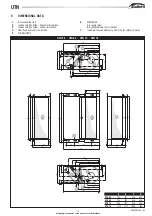
Page 15: ...1 D 208 45 C 15 D 15 32 208 40 280 5 280 40 173 67 C 15 D 15 2 3 7 7 3 2 4 A B C D UTN 06 754 707 676 646 UTN 08 754 707 676 646 UTN 12 964 917 886 856 UTN 16 1174 1127 1096 1066 9 DIMENSIONAL DATA 1...

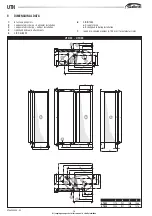
Page 16: ...AIR DELIVERY 6A 17 6B 88 375 170 718 B 23 A 23 D 227 45 15 D 15 C 45 352 275 32 15 D 15 C 74 198 294 208 273 392 365 473 523 617 135 204 28 53 17 188 165 100 57 215 294 208 273 392 382 506 510 579 98...

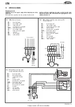
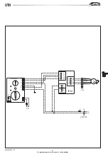
Page 17: ...lied M fan motor RD red low speed TA room thermostat WH white common N L S RL 4 1 2 3 4 5 6 7 8 9 WH BK GY BU RD 1 230 1 50 IL F CD CN GNYE M TC 10 2 UTN with CD remote three speed selector and TC fan...

Page 18: ...erface accessory IL mains switch not supplied M fan motor RD red low speed WH white common 230 1 50 9 8 7 6 5 4 M 1 GNYE L N F IL 2 1 N N RF c S RL 4 1 2 3 CN CD TA2 RD BU GY BK WH T SF 10 4 UTN with...

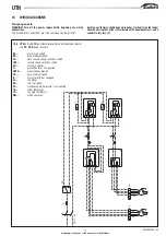
Page 19: ...low speed SF Centralised mode selector not supplied TA room thermostat TC fan stop thermostat WH white common L IL F N 9 8 7 6 5 4 M 1 SF CN RD BU GY BK WH 9 8 7 6 5 4 M 1 CN RD BU GY BK WH 1 2 3 4 5...

Page 20: ...C 9 8 7 6 5 4 CN M 1 WH BK BU GY RD 230 1 50 TC SF ACC T TDC GNYE 10 8 UTN units with TDC wall mounted control with speed selector and electromechanical thermostat BK black high speed BU blue medium s...

Page 21: ...m speed IL mains switch not supplied M fan motor RD red low speed SF centralised mode selector not supplied TD4T wall mounted control with speed selector electromechanicalthermostatandsummerwintersele...

Page 22: ...l p a n e l f o r t h e a u t o m a t i c c o n t r o l o f t h e f a n c o i l R D r e d l o w s p e e d S A R o o m t e m p e r a t u r e p r o b e f o r a u t o m a t i c f a n s p e e d s e l e c...

Page 23: ...R O D W a l l m o u n t e d m i c r o p r o c e s s o r c o n t r o l p a n e l R C H R e m o t e s w i t c h f o r t h e c e n t r a l i z e d c o o l i n g h e a t i n g m o d e s e l e c t i o n n...

Page 24: ...o d e b y m e a n s o f f a n s t a rt s t o p a t a m a n u a l l y s e t t e m p e r a t u r e T D C W a l l m o u n t e d c o n t r o l w i t h s p e e d s e l e c t o r a n d t h e r m o s t a t W...

Page 25: ...ls for in built MICROPRO and wall MICROPRO D installation complete with fan speed selector electronic thermostat and cooling heating mode selector for the automatic control of the fan working on the v...

Page 26: ...tc coupled to a flanged sleeve that represents the starting point for rectangular ducts of the type commonly used in distribution plants PCOF Connecting panel to flexible ducts Manufacturedingalvanise...

Page 27: ...ther flanged accessories They are made up of a rectangular panel that is to be secured to the machine or to another accessory with similar drilling i e MAF MAFO RE etc coupled by means of a flexible b...

Page 28: ...d maintenance Pay utmost attention during the maintenance operations accidentally coming into touch with some of the metallic parts might cause injuries therefore wear safety work gloves Every time th...

Reviews: