background image

© Copyright

Gallo Technologies

. All Right Reserved

- 8 -

Rev. V8.2- 20212

10. RFID Scan time:
Short (default):

Sets the interval between the RFID transmitter scans to a shorter period of time. Normal battery life

& shorter detection time. Preferred.

Long:

Sets the interval between the RFID transmitter scans to a longer period of time. Extended battery life but

longer detection time.

Note: If there is no RFID detection activity for 72 hours or more, the RFID scanner will turn OFF. Pressing
any button on the Key FOB will reactivate the RFID scanner.

11. Anti-hijack:
Enabled (default):

Turns ON Anti-Hijack Function. Anti-Hijack can be activated using the key FOB.

OFF:

Turns OFF Anti-Hijack Function. Anti-Hijack can not be activated using the key FOB

12. Ignition 2 Start Requirement:
Disabled (default):

Ignition 2 output turns ON during the engine start sequence and ON after the engine start

sequence.

Enabled:

Ignition 2 output is OFF during the engine start sequence but activated (ON) after the engine start

sequence.

13. Return Factory Default

: Resets all Function Options to factory default settings.

14. Car Window Close Time:
5 Sec (default)

Window close output pulse length set to 5 sec.

3 Sec (optional)

Window close output pulse length set to 3 sec.

15. Car Window Auto Close:
OFF (default)

Car window close function is turned OFF. Windows will not auto close after driver leaves the vehicle.

ON (optional)

Car Window close function is turned ON. Windows will auto close when driver leaves the vehicle. The

window close output will only activate

after the engine has been turned off

and the driver leaves the vehicle.

NOTE:

This function should only be used in conjunction with a

window close module

(not included) that limits the

current to the window motors in the event of an obstruction being in the way when the window is closed.

A. Code learning (code learning mode, for the new transmitters)

1. System must be in Disarm mode (green LED flashing).
2. Press the valet switch 3 times, then hold the valet switch for over 5 seconds, it will enter the code learning mode.

The green LED will light up and the parking lights will flash 2 times.

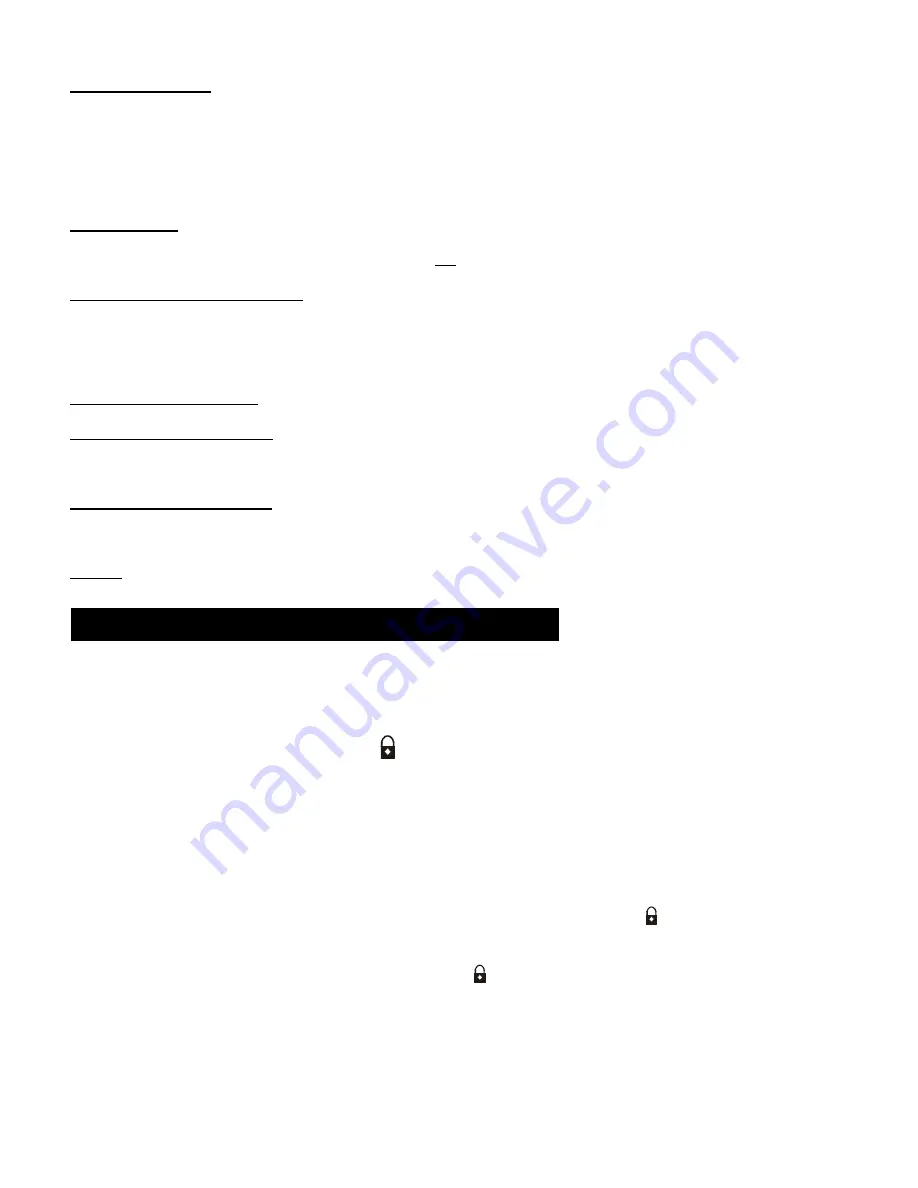
3. Immediately (within 5 seconds) press the

button on the new key FBO that needs to be code learned. When

the parking lights flash 4 times, code learning was successful. Repeat this process for the second Key FOB.
Both key FOBs must be code learned.

B. Function Programming:

1. System must be in Disarm mode (green LED flashing).
2. Press valet switch 5 times, then hold the valet switch for over 5 seconds, parking lights will flash 2 times.
3. According to the “Function Option Chart” below, you can set up the required function by pressing the Valet

Switch the number of times indicated in Table 1.

4. Immediately after pressing the valet switch the number of time indicated press the

button on the key FOB. If

the parking lights flash 3 times, the default setting for that function has been set. If the parking lights flash 1 time,
the alternate setting has been set.

Note: After entering the “Function Programming” mode, the

button must be pressed on the key FOB within 5

seconds. If not, the system will exit the “Function Programming” mode and the parking lights will flash 4 times.
Repeat steps 1 thru 4 for each additional programming function.

1.5 Key FOB & PROGRAMMING FUNCTION SET UP

Summary of Contents for GTStarter-2 GTS-2

Page 1: ...alled into a vehicle in which all systems and associated components are in perfect working condition DAMAGE to the GTStarter 2 unit resulting from incorrect installation or failure to follow guidelines stated in this manual will not be covered under warranty and will be subject to repair or replacement charges Links to nation wide Alarm installers can be found on our web site at www GalloTech com ...

Page 2: ...s as they are not compatible with GTStarter 2 To ease and reduce installation time we suggest you consider the following points before starting 1 Check all vehicle manufacturer cautions and warnings regarding electrical service AIR BAGS ABS BRAKES ENGINE BODY COMPUTER AND BATTERY Use extreme care and do not probe any wires of the SRS system 2 Additional vehicle specific wiring diagrams and other h...

Page 3: ...en when the FOB is within detection range of the vehicle When the small LED flashes red the key FOB battery should be replaced The four buttons on the RFID FOB can be used to activate deactivate other functions Lock Button Arm Remote Lock Panic Siren Stop a Arms the system and locks the doors with one press Siren will chirp once and parking lights flash once doors will lock The blue LED on the PUS...

Page 4: ... pressing the button will stop the siren The system will remain in the armed mode b Car Locating When the system is armed holding this button for more than 2 seconds the siren will chirp and the parking lights will flash five times c Anti Hijack When the engine is running holding the button for over 2 seconds the parking lights will flash twice and Anti Hijack mode will be started After 40 seconds...

Page 5: ...N 2 ON OFF with no engine start Press PUSH START STOP button and hold for 1 5 sec without pressing the brake clutch peddle ACC IGN 1 and IGN2 will turn ON and the engine will not start To turn ACC IGN1 and IGN2 OFF press and hold for 1 5 sec PUSH START STOP button or when the RFID key FOB is taken out of range ACC IGN1 and IGN2 will turn OFF automatically OFF ACC Ign1 IGN2 ON Press button for 1 5 ...

Page 6: ... alarm function will be disabled The key FOB buttons can lock and unlock doors but not the trunk Push Start Stop button functions will continue as in Normal status If the key FOB is in range the vehicle can be started with the Push Start Stop button or the ignition key if an ignition key switch is also used Transmitter Key FOB Code learning The Key FOBs have been matched to the control module at t...

Page 7: ...fault The system will not automatically rearm and relock itself after the system is disarmed by pressing if the door is not opened Enabled The system will automatically rearm and relock itself within 30 seconds after the system is disarmed by pressing if the door is not opened 6 Electrical Siren Horn Electrical Siren default Set if the 6 tone siren included is used Horn Set if the vehicle s horn i...

Page 8: ...has been turned off and the driver leaves the vehicle NOTE This function should only be used in conjunction with a window close module not included that limits the current to the window motors in the event of an obstruction being in the way when the window is closed A Code learning code learning mode for the new transmitters 1 System must be in Disarm mode green LED flashing 2 Press the valet swit...

Page 9: ...connecting this wire you must first find the BAT wire coming from the ignition switch The BAT wire is used to supply 12v battery power to the entire vehicle Solder connect the C1 RED wire w 35amp fuse to the BAT wire coming from the Ignition switch At the same time that you connect the C1 RED wire also solder connect the PINK fused wire from connector C4 C1 ORANGE Starter Output Before connecting ...

Page 10: ...the ignition key switch OR the Push Start Stop button Option 2 Use this wiring to energize Max 150 MA an optional relay when your vehicle uses both an IGN 1 IGN 2 circuits during Starting Run The relay AMP rating will need to be high enough to carry the load for your vehicle s IGN 2 circuit Option 3 For Automatic transmission connect Start Enable Input yellow wire to chassis ground Engine will onl...

Page 11: ...etermine the Door Locking Unlocking circuitry that your vehicle is equipped with Fig 2 shows the door lock unlock output relay configuration of the Control Module The majority of vehicles come equipped with either Neg Fig 3 or Pos Fig 4 Trigger circuits Find the location of the appropriate circuitry for your vehicle Make Model Year Diagrams can be found on our web site at www GalloTech com If the ...

Page 12: ... Copyright Gallo Technologies All Right Reserved 12 Rev V8 2 20212 Figure 3 Figure 4 Figure 5 Figure 6 ...

Page 13: ...itch terminal that has 12v only when foot brake is depressed C5 ORANGE Siren 12v Output Connect to the RED Siren wire Connect the second siren input BLACK wire to a good chassis ground If the vehicle s horn is used connect the ORANGE wire to the on the horn relay C5 BLACK Neg Ground Connection Connect the BLACK wire to a good chassis ground in a convenient location 3 PIN Wire Harness Push Start St...

Page 14: ...in the glove box so that it can be accessed from time to time to change or modify the programmable functions of GTStarter 2 Connect the 2 pin connector to the Control Module as shown in Figure 1 1 Recheck all electrical connections to be certain they are connected in the proper locations and check that all connections are wrapped with a good quality electrical tape or shrink tubing 2 Connect all 1...

Page 15: ...ssed If the clutch peddle switch is Pos when the clutch is pressed then a relay is required to reverse the input to Neg Also check Table 1 for correct transmission selection AN ACCESSORY RADIO HEATER FAN ETC DOES NOT TURN OFF DURING ENGINE CRANKING AND OR TURN BACK ON AFTER CRANKING a Check the connections of C1 wire harness for the correct connection points See Figure 1 There are usually only two...

Reviews: