background image

-2- 

Wire Size and Termination


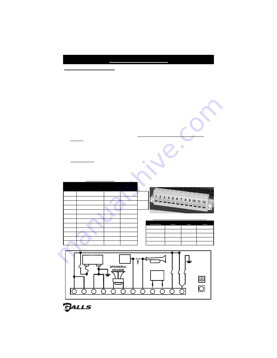
Electrical connections to this unit are made through the green 12-terminal 
connector located in the rear of the unit 

(See below - Part # CPSS-153)


Examine the charts below to determine the proper gauge of the wire to use.  Please 
review the following recommendations when making your electrical connections: 


• 

For safety and reliability we highly recommend that you always use both Power 
terminals (1 & 2) and both Ground terminals (3 & 4). 


• 

Use only high quality crimp connectors.  Make sure all connections are tight. 


• 

Minimize the number of splices to reduce voltage drop. 


• 

Route wiring to prevent wear, overheating, and interference with air bag 
deployment. 


• 

Use grommets and sealant when passing through compartment walls.   


• 

Ground connections should be made 

directly to the negative of the vehicle 

battery

.  Where not possible, only connect to substantial chassis components. 


• 

Install and check all wiring before connection to vehicle battery.  


• 

CAUTION: All wires should be rated for at least 125% of their maximum current 
load.  All wires connected to the positive terminal of the battery should be fused 
at the battery for their rated load.  


• 

Review the charts below that indicate the recommended wire gauge, based 
upon the length of the wire run and the current that will pass through the wire. 

Terminal


Description


Typical 

Color


Typical 

Current


1


Power


Red


10A


20A 

Total


2


Power


Red


10A


3


Ground


Black


10A


4


Ground


Black


10A


5


Speaker 1


Brown


4A


6


Speaker 2


Brown


4A


7


AUX In


Green


3A


8


AUX Out


Orange


3A


9


Radio Repeat


Blue


0.1A


10


Radio Repeat


Blue


0.1A


11


Backlighting


Yellow


0.1A


12


Park/Kill Input


White


0.1A


20A 

Total


WIRING GUIDE


Current


10'


20'


25'


< 2.0A 

22 AWG 

18 AWG 

18 AWG 

2.0-4.0A 

18 AWG 

16 AWG 

16 AWG 

4.1-5.5A 

18 AWG 

16 AWG 

14 AWG 

5.6-8.0A 

16 AWG 

14 AWG 

14 AWG 

8.1-12.0A 

16 AWG 

12 AWG 

12 AWG 

RECOMMENDED WIRE GAUGE


Electrical Connections 

B

a

c

k

lig

h

ti

n

g

 P

o

w

e

r

A

U

X

 I

n

Factory

Horn

Relay

G

ro

u

n

d

P

o

w

e

r

+

-

20A 

Fuse

Ig

n

it

io

n

 S

w

it

c

h

BATTERY

12V

POS

NEG

S

S

7

0

0

C

u

F

a

c

to

ry

 W

ir

e

2 Way

Radio

Speaker

-

+

O

R

Factory Horn

12

11

P

a

rk

 K

ill

A

U

X

 O

U

T

10

8

7

6

5

4

3

2

1

9

WARNING: ENSURE CONNECTOR  IS FULLY INSERTED & SCREWS LOCKED

A

U

X

 P

O

L

A

R

IT

Y

TONE

SELECT

P

K

 P

O

L

A

R

IT

Y

CPSS-153 

(Please note that this is an upside-down view)


(Please note that this diagram references the connector with the siren UPSIDE-DOWN) 

(SIREN TOP) 

Summary of Contents for Street Thunder ST240

Page 1: ...944 2557 www galls com NOTICE Due to continuous product improvements we must reserve the right to change any specifications and information contained in this manual at any time without notice Galls an...

Page 2: ...NECTIONS 2 3 Wiring Guide 2 Wiring Diagram 2 Mandatory Connections 3 Optional Connections 3 INSTALLER SELECTABLE OPTIONS 4 5 DIP Switch Settings AUX P K Polarity 4 Optional Tone Programming 4 5 OPERAT...

Page 3: ...ears of safe reliable operation Please read all instruction before installing the unit Failure to follow these instructions can cause serious damage to the unit or vehicle and may void warranties Qual...

Page 4: ...o the positive terminal of the battery should be fused at the battery for their rated load Review the charts below that indicate the recommended wire gauge based upon the length of the wire run and th...

Page 5: ...n in HF mode see page 6 Air Horn activation or Manual step up function see page 5 If you will be using any of these features cut the wire that connects the horn relay to the horn Connect the side from...

Page 6: ...lectable Options Optional Tone Programming The ST240 will produce 7 different tones sounds by activating its various functions Function Default Tone Thunder Step Up THUNDER MAN Two Tone THUNDER Thunde...

Page 7: ...y default the Wail tones indicated by the above will wind down when they are de activated If you prefer to have them immediately stop i e hard stop hold the Program Button for 3 seconds until the LED...

Page 8: ...ols the primary operating function of the siren THUNDER Ultra fast changing tone used for maximum attention YELP A rapidly changing tone used in congested areas WAIL A slower changing tone used on hig...

Page 9: ...way momentary switch for the Manual function and the Air Horn Radio Volume The radio repeat volume VOL control is recessed in the upper left hand corner of the front face This should be set when the...

Page 10: ...turned on Does microphone button release properly Is the PK jumper option properly configured Does the siren work when Park Kill input is disconnected Check for a short Check for an open No PA PA vol...

Page 11: ...Amps 13 6 VDC dual 100W speakers Standby Current Switch Off Backlighting Off Less than 4 mA Switch On Backlighting Off Less than 7 mA Switch Off Backlighting On Less than 40 mA Switch On Backlighting...

Page 12: ...aser During this warranty period the obligation of Galls is limited to repairing or replacing as Galls may elect any part or parts of such product which after examination by Galls is determined to be...

Reviews: