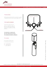
ASSEMBLY INSTRUCTIONS
B.
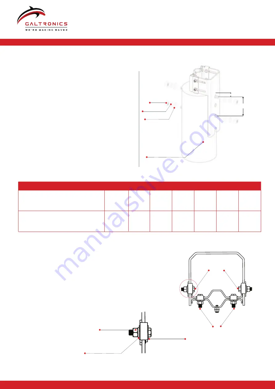
Assemble right bracket stopper plates and left bracket (Clamping brackets)
Use 7/16” fasteners to attach the support bracket,
stopper plates and left brackets without tightening (see details).
For a pole with diameter between 9” - 12”, position the interlock
tabs of the stopper plates towards the support
bracket (see picture detail on the left).
For 6” - 9” pole diameters position, the interlock tabs
away from the support backet.
Tightening hardware to the final position
will be done after placing the antenna
on the pole!
Table 1.1 - Threaded rod length
Pole diameter:
8”
(203mm)
9”
(228mm)
11”
(279mm)
12”
(305mm)
6”
(152mm)
9”
(228mm)
7”
(177mm)
10”
(254mm)
11”
(279mm)
12”
(305mm)
10”
(254mm)
13”
(330mm)
14”
(255mm)
15”
(381mm)
Threaded rod length:
7/16“ X 11/2”
7/16“ X 11/2”
A.
Attach support bracket to pole
Drill required hole (Ø 1.1”) through the
wooden pole (see drawing).
Attach the support bracket to the
wooden pole.
Our recommendation:
Use 1” threaded rods and corresponding 1”
plain washer, spring washers and
1″ Nut
as shown
in the drawings.
Tighten with a torque of 150Nm (1328 In*Lbs).
Choose threaded rod length according to
Table 1.1.
1
″
Plain Washer
1
″
Sping Washer
1
″
Nut
7/16“ Nut
7/16“ Plain and
Spring Washer
7/16“ Plain Washer
w w w . g a l t r o n i c s . c o m
Copyright © 2016 – Galtronics Corporation Ltd.
Proprietary Information. All rights reserved. Galtronics reserves the right to modify or amend any antenna or specifi
cation without prior notice.
21-234-03 R
elease Date:16
th
September, 2
016; Revision: S-
4; Patent Pending
Baylin TechnOlogies Company
Model No:
62-20-09 |
Mounting instructions outdoor DAS antennas
page 3 of 4
1.57” (40mm)
6.9” (175mm)
Wooden Pole
(Ø6” to Ø12”)


