15
EN
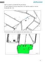
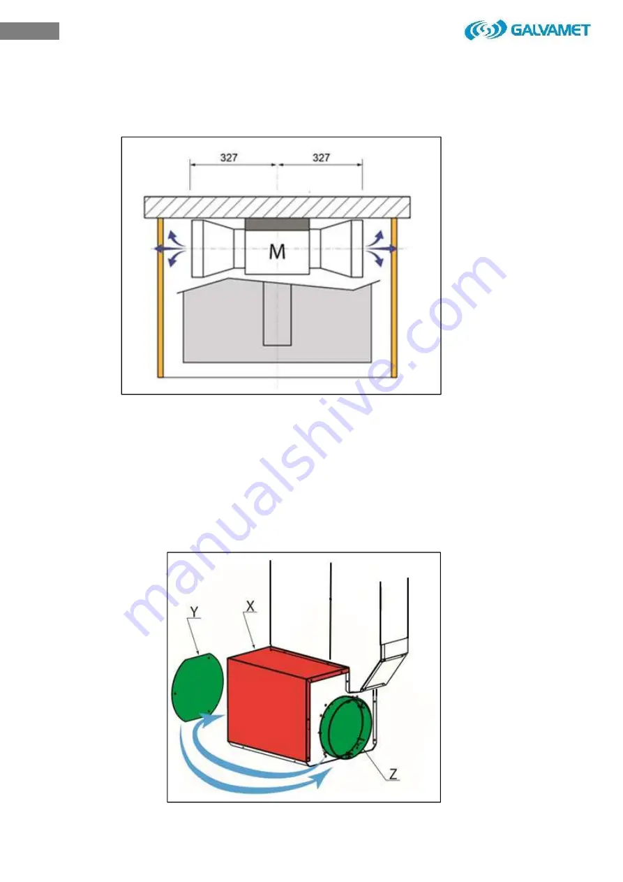
The next step is to determine the exit of the fumes according with the installation needs
(Fig. 3.15).
The air exit can be on the left or on the right of the kitchen base. To carry this
operation out it is necessary to remove the covers (Fig. 3.16-X), (Fig. 3.16-Y), invert
the motor exit. Then proceed with the same operations backwords, fix the cover
(Fig. 3.16-Y) on the opposite side and install the covering. (Fig. 3.16-X).
The air exit can be rear or front by connecting a bend pipe not included.
Fig. 3.16
Fig. 3.15
Summary of Contents for KompaKOne
Page 1: ...IT KompaKOne ISTRUZIONI PER L USO E LA MANUTENZIONE 230 240Vac 50Hz 395 479 6 ...
Page 2: ...2 IT ...
Page 75: ...75 IT ...
Page 77: ...EN KompaKOne INSTALLATION OPERATING AND MAINTENANCE GUIDE 230 240Vac 50Hz 395 480 6 ...
Page 78: ...2 EN ...
Page 153: ...DE KompaKOne BEDIENUNGS UND WARTUNGSANLEITUNG 230 240Vac 50Hz 395 481 6 ...
Page 154: ...2 DE ...
Page 227: ...75 DE ...
Page 229: ...ES KompaKOne INSTRUCCIONES DE USO Y MANTENIMIENTO 230 240Vac 50Hz 395 482 6 ...
Page 230: ...2 ES ...
Page 256: ...28 ES Fig 3 19 ...
Page 305: ...FR KompaKOne MANUEL D EMPLOI ET D ENTRETIEN 230 240Vac 50Hz 395 497 6 ...
Page 306: ...2 FR ...
Page 379: ...75 FR ...


