background image


Parts Identification 

& Manual Service


4/40 

Issue 1.0 

Ref. NR-00126-ENG 

http://www.gamapur.com/


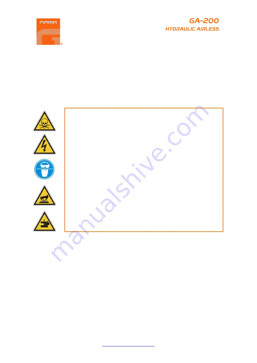
When  working  with  the  unit,  it  is  recommended  that  the  operator  wear  suitable  clothing  and 
elements of personal protection, including, without limitation, gloves, protective goggles, safety 
footwear  and  face  masks.    Use  breathing  equipment  when  working  with  the  machine  in 
enclosed  spaces  or  in  areas  with  insufficient  ventilation.    The  introduction  and  follow-up  of 
safety measures must not be limited to those described in this manual.  Before starting up the 
machine, a comprehensive analysis must be made of the risks derived from the products to be 
dispensed, the type of application and the working environment 


To  prevent  all  possible  bodily  harm  caused  by  incorrect  handling  of  the 
raw materials and  solvents used in the process, carefully read the safety 
information provided by your supplier.  

Deal with the waste caused according to current regulations. 

Disconnect  the  unit  from  the  power  supply  before  carrying  out  any 
operation inside the electrical console. 

The  electrical  maintenance  of  the  machine  must  only  be  performed  by  a 
qualified electrician. 

To avoid damage caused by the impact of pressurized fluids, do not open 
any  connection  or  perform  maintenance  work  on  components  subject  to 
pressure until the pressure has been completely eliminated. 

Use  suitable  protection  when  operating,  maintaining  or  remaining  in  the 
operating area of the unit.  This includes, but is not limited to, the use of 
masks, protective goggles, gloves, shoes and safety clothing. 

The  unit  includes  components  that  reach  temperatures  that  are  liable  to 
cause  burns.    The  hot  parts  of  the  unit  must  not  be  handled  until  they 
have cooled. 

To  prevent  serious  harm  by  crushing  or  loss  of  limbs,  do  not  work  with 
the  unit  without  the  safety  guards  installed  on  all  moving  parts.    Make 
sure  that  all  of  the  safety  protections  are  correctly  reinstalled  after  all 
repair or maintenance work is completed. 


Summary of Contents for GA-200

Page 1: ...up carefully read all the technical and safety documentation included in this manual Pay special attention to the information to know and understand the handling and the conditions of use of the unit...

Page 2: ...oduct Use of heating devices pumping equipment dispensers or other parts or accessories with the Product that have not been approved or manufactured by HI TECH Failure to follow the operating instruct...

Page 3: ...the operation and the conditions of use of the unit All of the information is aimed at enhancing User Safety and avoiding possible breakdowns derived from the incorrect use of the unit WARNING Establi...

Page 4: ...ier Deal with the waste caused according to current regulations Disconnect the unit from the power supply before carrying out any operation inside the electrical console The electrical maintenance of...

Page 5: ...pressure Do not exceed the maximum working pressure of any component or accessory used in the system FIRE OR EXPLOSION HAZARD Static electricity is created by the flow of fluid through the pump and h...

Page 6: ...he pump must be connected to ground The pump must be connected to ground with a ground wire which is supplied with the pump 4mm2 of section and a clamp GASOLINE ENGINE SAFETY Honda engines are designe...

Page 7: ...oxide gas exposure may cause loss of consciousness and may lead to death The muffler becomes very hot during operation and remains hot for a while after stopping the engine Be careful not to touch the...

Page 8: ...electric motor a To start the gas engine Move the fuel valve lever to the open position Move the throttle lever to its middle point Move the choke lever to the closed position for a cold engine or to...

Page 9: ...ve located on the hydraulic pressure hose The handle should be in line with the hose Open the bleed valve by turning it fully counter clockwise Start the engine or turn on the electric motor a To star...

Page 10: ...rning the pressure control knob slowly clockwise Check the entire system for leaks If leaks occur follow the Pressure Relief Procedure in this manual before tightening any fitting or hoses Follow the...

Page 11: ...h to the OFF position Remove the bleed hose from the waste container and place it into the container of paint Close the bleed valve by turning it fully clockwise Start the engine or turn on the electr...

Page 12: ...trigger lock to the locked position Turn off the unit a To turn off the gas engine Set the pressure to minimum by turning the pressure control knob fully counter clockwise Move the throttle lever to t...

Page 13: ...presence of flammable vapours Follow the Pressure Relief Procedure found in the Operation section of this manual Remove the gun tip and tip guard and clean with a brush using the appropriate solvent...

Page 14: ...the Operation section of this manual Store the unit in a clean dry area WARNING Do not store the unit under pressure CLEANING A CLOGGED TIP 1 Follow the Pressure Relief Procedure in the Operation sec...

Page 15: ...the paint MAINTAINING THE HYDRAULIC SYSTEM CAUTION Use of Hydraulic Fluid DIN 51524 standard section 1 2 for example ISO VG 46 is mandatory in the hydraulic system Do not use any other hydraulic fluid...

Page 16: ...cal Honda dealer ENGINE OPERATION SERVICE 1 Clean and oil air filter pad on gasoline engine every 25 hours or once weekly Do not permit the air intake screen around the fly wheel of the gas engine to...

Page 17: ...flow through siphon hose Bottom ball stuck to foot valve seat Siphon hose is kinked or loose Refill with new material If too thick remove siphon hose immerse fluid section in material and start pump t...

Page 18: ...wn Replace valve and spool in this condition Check trip rod for possible separation and spool in this condition Check trip rod for possible separation Oil motor stalls at top no unusual heat problems...

Page 19: ...3306 psi 228 bar Max Production _____________________________________________6 4 l min 1 69 gal min Maximum PCD size ________________________________________________ 1 gun 0 043 _____________________...

Page 20: ...Parts Identification Manual Service 20 40 Issue 1 0 Ref NR 00126 ENG http www gamapur com Figure 1 GA 200 model General Description GENERAL DESCRIPTION...

Page 21: ...ontrol 5 Hydraulic Fluid Level 6 On Off Switch 7 Hydraulic Tank 8 Hydraulic Filter 9 Electric Motor 4 HP 3kW 220v 50Hz GA 200 E Gasoline Engine Honda 5 5 HP 4 1 kW GA 200 G 10 Trolley 11 Inlet Hydraul...

Page 22: ...Parts Identification Manual Service 22 40 Issue 1 0 Ref NR 00126 ENG http www gamapur com Figure 2 Motor Pump Parts List MOTOR PUMP...

Page 23: ...6 O Ring ASP 12 2 7 Plug ASP 13 2 8 Nipple ASP 14 1 9 Nut ASP 15 1 10 Valve ASP 16 1 11 Shaft ASP 17 1 12 Distributor ASP 18 1 13 O Ring ASP 19 3 14 Washer ASP 20 1 15 Washer ASP 21 1 16 Nut ASP 22 1...

Page 24: ...ce 24 40 Issue 1 0 Ref NR 00126 ENG http www gamapur com Item Description Part Number Qty 30 Valve ASP 36 1 31 Guide ASP 37 1 32 Nipple ASP 38 1 33 Pipe ASP 39 1 34 Elbow ASP 40 1 35 Motor Pump Rebuil...

Page 25: ...Parts Identification Manual Service 25 40 Issue 1 0 Ref NR 00126 ENG http www gamapur com Figure 3 Displacement Pump Parts List DISPLACEMENT PUMP...

Page 26: ...4 Packing ASP 44 6 5 Packing ASP 45 4 6 Male Gland ASP 46 2 7 Spring ASP 47 1 8 Joint ASP 48 2 9 Cylinder ASP 49 1 10 Spring Seat ASP 50 1 11 Spring ASP 51 1 12 Ball ASP 52 1 13 Piston ASP 53 1 14 Cyl...

Page 27: ...ww gamapur com Figure 4 Hydraulic System Parts List Table 5 Hydraulic System Parts List Item Description Part Number Qty 1 Tank ASP 68 1 2 Cover ASP 69 1 3 Valve ASP 70 1 4 Joint ASP 71 1 5 Screw ASP...

Page 28: ...18 Elbow ASP 85 1 19 Pipe ASP 86 1 20 Nipple ASP 87 1 21 Knop ASP 88 1 22 Plate ASP 89 1 23 Pulley ASP 90 1 24 Pin ASP 91 1 25 Screw ASP 92 1 26 Cover ASP 93 1 27 Filter ASP 94 1 28 Elbow ASP 95 1 29...

Page 29: ...Parts Identification Manual Service 29 40 Issue 1 0 Ref NR 00126 ENG http www gamapur com Figure 5 Model with Electric Motor Parts List MODEL WITH ELECTRIC MOTOR...

Page 30: ...P 109 1 2 Pin ASP 110 1 3 Washer ASP 111 8 4 Screw ASP 112 2 5 Washer ASP 113 4 6 Nut ASP 114 2 7 Handle ASP 115 1 8 Plate ASP 116 1 9 Motor ASP 117 1 10 Switch On Off ASP 118 1 11 Plug ASP 119 1 12 C...

Page 31: ...Parts Identification Manual Service 31 40 Issue 1 0 Ref NR 00126 ENG http www gamapur com Figure 6 Model with Gasoline Engine Parts List MODEL WITH GASOLINE ENGINE...

Page 32: ...ngine Parts List Item Description Part Number Qty 1 Pulley ASP 125 1 2 Pin ASP 110 1 3 Washer ASP 123 8 4 Screw ASP 112 4 5 Washer ASP 124 4 6 Nut ASP 114 4 7 Handle ASP 115 1 8 Plate ASP 126 1 9 Moto...

Page 33: ...escription Part Number KIT HP FILTER DRAIN VALVE WHEN SPRAYING PAINTS ASP 128 CARBON STEEL 1 150 kg ASP 129 ALUMINIUM 0 900 kg ASP 130 CARBON STEEL 1 830 kg ASP 131 ALUMINIUM 1 430 kg ASP 132 SWIVEL C...

Page 34: ...RLESS GUN FILTER 50 MESH COLOR WHITE ASP 136 100 MESH COLOR YELLOW ASP 137 200 MESH COLOR RED ASP 138 Airless GUN see specific chapter in sheet 36 ASP 02 HOSES 1 4 x 1 m 3 28 ft ASP 01 1 4 x 15 m 49 2...

Page 35: ...E SIZE Part Number Fan Width at 300 mm FLOW Litres min AUTO CLEAN TIP ASP 04 XX XX 0 89 mm 0 035 ASP 04 35 40 200 250 435 4 96 0 68 mm 0 027 ASP 04 27 60 300 350 627 2 91 0 58 mm 0 023 ASP 04 23 20 10...

Page 36: ...www gamapur com Figure 7 Airless Gun ASP 02 model Parts List Weight with packaging 0 620 kg 1 37 lb Weight without PCD 0 530 kg 1 17 lb Dimensions of packaging 235 x 175 x 47 9 25 in x 6 89 in x 1 85...

Page 37: ...n ASP 152 1 8 Shaft ASP 153 2 9 Needle Handle ASP 154 1 10 Nut ASP 155 1 11 Filter 50 Mesh ASP 136 2 12 Handle Gun ASP 156 1 13 Swivel Union ASP 157 1 14 Joint ASP 158 1 15 Trigger Guard ASP 159 1 16...

Page 38: ...with the empty fuel tank When ordering you can choose the type of motor you want on the unit E electrical or G gasoline All orders will include a gun ASP 02 with the standard configuration o Gun Assem...

Page 39: ..._____________________________________________________________________16 FIRST 20 HOURS______________________________________________________________16 EVERY 100 HOURS__________________________________...

Page 40: ...0 Table 7 Model with Gasoline Engine Parts List__________________________________ 32 Table 8 Airless Gun ASP 02 model Parts List___________________________________ 37 Figure 1 GA 200 model General Des...

Reviews: