


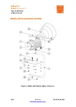
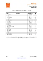
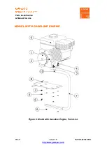
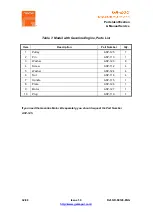

Parts Identification
& Manual Service
17/40
Issue 1.0
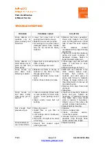
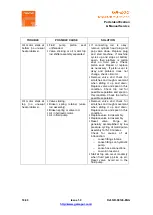
TROUBLE
POSSIBLE CAUSE
SOLUTION
Pump delivers on
upstroke only or
goes up slowly and
down fast.
▪
Lower foot valve ball is not
seating due to trash or wear.
▪
Material too viscous to siphon.
▪
Air leaking in on siphon side or
damaged siphon hose. Siphon
may be too small for heavy
material.
▪
Remove foot valve assembly.
Clean and inspect. Test foot
valve by filling with water; if ball
fails to seal the seat, replace
ball.
▪
Thin
material,
contact
manufacturer for proper thinning
procedures.
▪
Tighten all connections between
pump and paint container. If
damaged, replace. Switch to
larger diameter siphon set.
Pump delivers on
down stroke only or
goes up fast and
down slowly.
▪
Upper ball is not seating due to
trash or wear.
▪
Lower packing set is worn.
▪
Check upper seat and ball with
water. If ball fails to seal,
replace seat.
▪
Replace packing set if worn.
Pump moves up
and
down
fast,
delivering material.
▪
Material container is empty or
material is too thick to flow
through siphon hose.
▪
Bottom ball stuck to foot valve
seat.
▪
Siphon hose is kinked or loose.
▪
Refill with new material. If too
thick, remove siphon hose,
immerse
fluid
section
in
material, and start pump to
prime. Add thinner to material.
Change to bigger siphon set.
Open bleed valve to remove air
and restart pump.
▪
Remove foot valve. Clean ball
and seat.
▪
Straighten.
Pump moves up
and down slowly
when spray gun is
shut off.
▪
Loose connections. Bleed valve
is open partially or bleed valve
is worn. Lower packing seat is
worn.
▪
Upper and/or lower ball not
seating.
▪
Check all connections between
pump and gun. Tighten as
necessary. If material is flowing
from bleed hose, close bleed
valve or replace, if necessary.
Should none of the above be
evident, replace lower packing.
▪
Reseat balls by cleaning.
Not enough fluid
pressure at gun.
▪
Spray tip is worn.
▪
Outlet filter or gun filter is
clogged.
▪
Low voltage and/or inadequate
amperage.
▪
Hose size or length is too small
or too long.
▪
Replace.
▪
Clean or replace filter.
▪
Check
electrical
service.
Correct as required.
▪
Increase hose size to minimize
pressure drop through hose
and/or reduce hose length.
Pump chatters on
up or down stroke.
▪
Solvent
has
caused
upper
packing to swell.
▪
Replace packing.
TROUBLESHOOTING


