background image

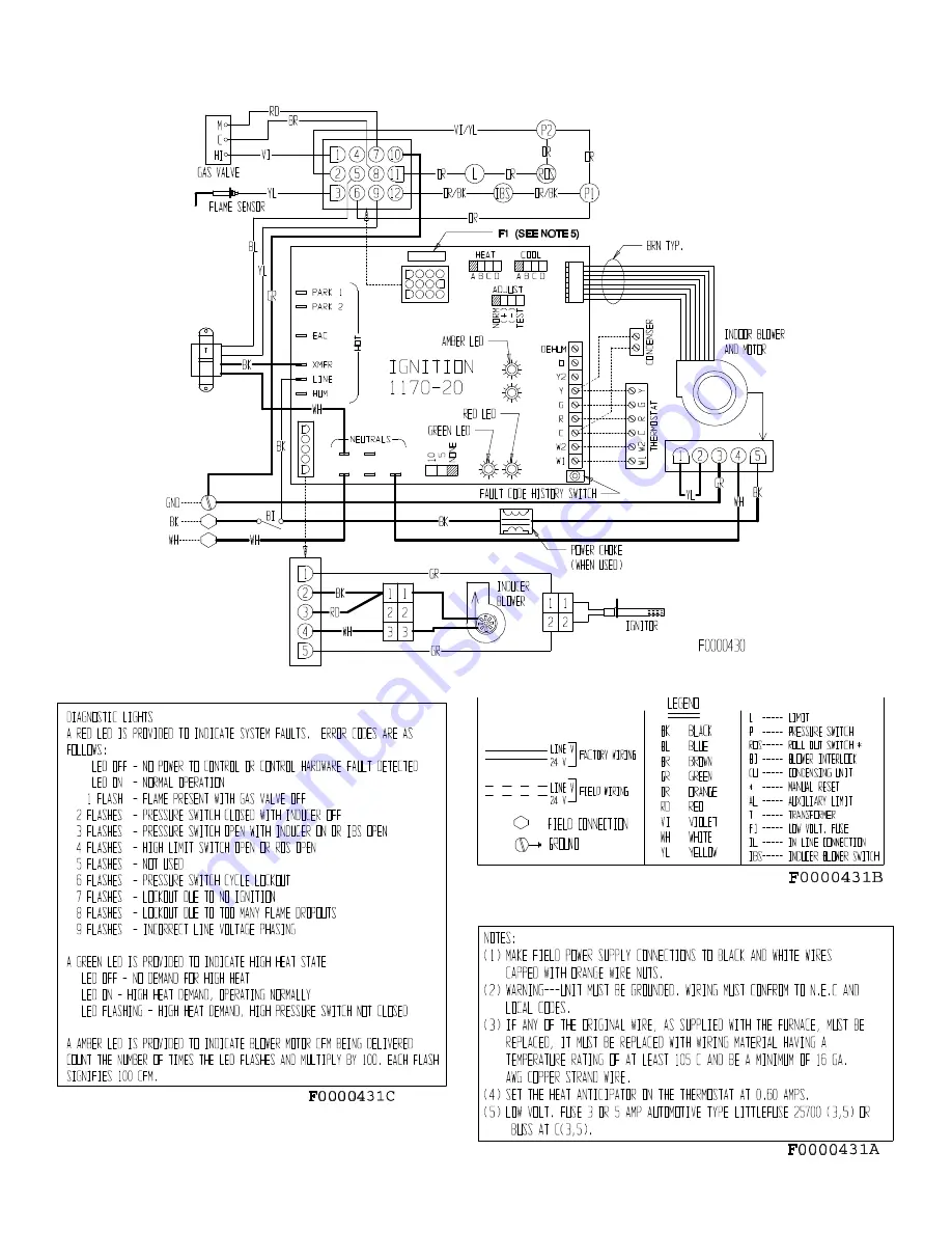
FURNACE WIRING SPECIFICATIONS

20558801

Issue 0442

Page 5 of 32

Summary of Contents for Gas-Fired Furnace

Page 1: ...E FURNACE HOMEOWNER RETAIN THESE INSTRUCTIONS FOR FUTURE REFERENCE INSTRUCTIONS D ENTRETIEN ET INSTALLATION ET MANUEL DE L USAGER INSTALLATEUR PLACEZ LA POCHETTE D INSTRUCTIONS À COTÉ DU GÉNÉRATEUR D AIR CHAUD PROPRIÉTAIRE CONSERVEZ CES INSTRUCTIONS POUR Y RÉFÉRER PLUS TARD LITERATURE BOOKLET NO 20557401 ISSUE 0442 20536912 ...

Page 2: ...FURNACE MARKINGS IN FRENCH CONSULT WITH YOUR DEALER OR LOCAL DISTRIBUTOR HAVE AVAILABLE THE MODEL NO AND SERIAL NO LOCATED ON THE UNIT RATING PLATE TO INSURE THE CORRECT FRENCH INSTRUCTION PACKET POUR OBTENIR DE LA DOCUMENTATION EN FRANÇAIS À L ATTENTION DE L INSTALLATEUR OU DU PROPRIÉTAIRE POUR OBTENIR LES INSTRUCTIONS D INSTALLATION LE MANUEL DE L USAGER ET LES MARQUAGES EN FRANÇAIS CONSULTEZ VO...

Page 3: ...The CSA International symbols on each nameplate is your assurance that your furnace design meets nationally recognized standards for safety and performance Do not store or use gasoline or other flammable vapors and liquids in the vicinity of this or any other appliance What to do if you smell gas Do not try to light any appliance Do not touch any electrical switch do not use any phone in your buil...

Page 4: ... gas on page 1 if the odor of gas is present Use only your hand to adjust the gas control switch never use tools If the switch will not move by hand don t try to repair it call a qualified service technician Force or attempted repair may result in a fire or explosion Do not use this furnace if any part has been under water A flood damaged furnace is extremely dangerous Attempts to use the furnace ...

Page 5: ...he thermostat to the temperature you would like the system to maintain Fan Operation You may wish to increase your comfort by setting your system for continuous air circulation of the indoor air The fan switch on the thermostat permits you to do this With the switch in the ON position the fan will operate continuously AUTO position gives fan operation only when the unit is in either heating or coo...

Page 6: ... to the beginning of the heating season and another during the middle Should you observe unusual amounts of any of the following conditions it is important that you call your authorized dealer at once to obtain a qualified service inspection Rust flakes or other deposits Coatings Corrosion Even if no unusual rust or other conditions are observed it is recommended that the furnace be inspected and ...

Page 7: ...air filter should be inspected at least every 6 weeks and cleaned or replaced as required Your furnace may use either a disposable filter permanent filter electronic or high efficiency media air cleaner Consult filter cleaner manufacturer for maintenance service and static pressure drop for air moving requirements Permanent filters may be replaced with disposable filters Refer to Table 1 when sele...

Page 8: ... be based on the manufacture date code Failure to follow the correct warranty procedure could result in disallowance of warranty claim PARTS REPLACEMENT INFORMATION GUIDE CASING GROUP GAS CONTROL GROUP BLOWER GROUP Top Panel Manifold Blower Housing Front Door Burner Blower Motor Blower Door Shield Top Bottom Blower Wheel Burner Access Door Orifice Capacitor Control Access Door Ignitor Blower Suppo...

Page 9: ...asoline or other flammable vapors and liquids in the vicinity of this or any other appliance Installation and service must be performed by a qualified installer service agency or the gas supplier Installation by an unqualified person may lead to equipment damage and or a hazardous condition which may cause bodily injury and harm and as such at the sole discretion of the manufacturer the entire war...

Page 10: ...by the installer On direct vent systems the vent outlet shall be installed so as to be in the same atmospheric pressure zone as the combustion air intake 6 Never test for gas leaks with an open flame Use a commercially available soap solution made specifically for the detection of leaks to check all connections as specified in The Gas Connection section on page 19 of these instructions 7 Always in...

Page 11: ...T A B C D E F G H EV050U3 29 1 2 13 1 2 47 3 8 11 1 2 18 15 16 12 21 5 8 2 15 9 9 14 45 55 131 EV075U3 29 1 2 13 1 2 47 3 8 11 1 2 18 15 16 12 21 5 8 2 15 9 9 14 50 60 140 EV100U4 29 1 2 17 47 3 8 15 18 15 16 15 1 2 21 5 8 2 15 11 8 14 50 60 167 EV125U5 29 1 2 20 1 2 47 3 8 18 1 2 18 15 16 19 21 5 8 2 20 15 12 50 60 193 SEE TABLES 3 AND 4 ON PAGES 15 AND 16 FOR ALLOWABLE MAX VENT AND AIR INLET LEN...

Page 12: ...0 HIGH FIRE 1550 1360 1190 1020 850 EV125U5 1 12 X 12 NORM A NORM 2000 1800 1600 1400 LOW FIRE 1250 2200 2070 1840 1610 HIGH FIRE 1940 1700 1530 1360 1190 When operating the furnace in the heating mode the static pressure and the temperature rise supply air temperature minus return air temperature must be within those limits specified on the rating label Failure to follow this warning could lead t...

Page 13: ...FURNACE WIRING SPECIFICATIONS 20558801 Issue 0442 Page 5 of 32 ...

Page 14: ... Z223 1 NFPA 54 or Canadian Natural Gas and Propane Installation Codes CSA B149 1 For complete information on installation standards consult the U S National Fuel Gas Code obtainable from the National Fire Protection Association Inc Batterymarch Park Quincy MA 02269 or the American Gas Association 1515 Wilson Boulevard Arlington VA 22209 or the Canadian installation codes obtainable from Canadian ...

Page 15: ... to be suspended from the ceiling it will be necessary to use steel pipe straps around each end of the furnace These straps should be attached to the furnace with sheet metal screws and to the rafters with bolts The furnace may also be suspended by using an angle iron frame bolted to the rafters See Table on page 3 for size and weight of furnace Care must be taken to allow for service access If a ...

Page 16: ...e shall be located so as not to interfere with proper circulation of air In addition to air needed for combustion ventilation in the form of process air must be provided as required for cooling of equipment or material controlling dew point heating drying oxidation or dilution safety exhaust and odor control Air must be supplied for ventilation including all air required for comfort and proper wor...

Page 17: ...0 000 60 000 80 000 100 000 120 000 140 000 160 000 100 100 100 100 120 140 160 12 12 12 12 13 14 15 EXAMPLE 50 000 Btuh Furnace 10 000 Btuh Water Heater 60 000 Btuh Total Input 12 Dia Round Duct If ventilation and or combustion air must be supplied to the Confined Space from outside the building structure two permanent openings to the outdoors must be created Each opening must have a free area of...

Page 18: ...on of rectangular air ducts must not be less than 3 inches Each opening must have a free area of not less than one square inch per 2 000 Btu per hour of total input of all appliances within the Confined Space These openings must be located 12 in from the top and bottom of the furnace area Neither opening can be blocked at any time See Figure 6 Figure 6 CONFINED SPACE OUTDOOR AIR THROUGH HORIZONTAL...

Page 19: ...he blower inlet there should be at least one 90 air turn between blower and return grille Further reduction in sound can be accomplished by installing acoustical air turning vanes and or lining the inside of the duct with acoustical material 4 It is recommended that the supply duct be provided with a removable access panel This opening shall be accessible when the furnace is installed and shall be...

Page 20: ...ards PVC primer and solvent cement used to secure all PVC joints must conform to ASTM D2564 Common venting with other condensing appliances or non condensing appliances is not allowed In all direct vent two pipe instances the vent outlet shall be installed so as to be in the same atmospheric pressure zone as the combustion air intake All combustion air and exhaust piping must be installed in accor...

Page 21: ...Figure 8 20558801 Issue 0442 Page 13 of 32 VENT TERMINATION CLEARANCES ...

Page 22: ...280901 Cat No 87L83 or 3 diameter Part No 20280902 Cat No 87L84 may also be used for horizontal side wall vent termination 2 diameter concentric vent approved for use with 50 and 75 models only Special consideration for this termination system should be given to 1 possible damage from the vapors to plants shrubs other equipment and building materials 2 possible damage to the terminal from foreign ...

Page 23: ...r venting is 5 ft and one 1 elbow Concentric vent kit terminated systems must use Direct Vent 2 pipe System allowable max vent lengths for the appropriate diameter pipe Refer to Tables 3 and 4 for the proper pipe diameters and maximum allowable vent lengths TABLE 3 Allowable Max Vent Lengths for 2 Diameter Venting APPLICATION Allowable Max Vent Lengths of 2 dia PVC ABS or CPVC SCH 40 Pipe Elbows A...

Page 24: ... elbow onto inducer outlet See Figure 17 and 18 Face elbow at appropriate casing side and secure using attached pipe clamp 2 Using 2 diameter SCH 40 PVC ABS or CPVC pipe install a short piece of pipe into the elbow The pipe should be long enough to leave approximately one inch 1 protruding out of the casing side minimum for connection to another fitting Transitions must be mounted to allow condens...

Page 25: ...ol pumping units and dryer vents To Convert from Upflow to Horizontal Left Airflow This furnace is shipped for installation in the upflow configuration but may be installed in a horizontal right to left airflow direction The changes needed to convert to the horizontal position are 1 Disconnect hoses from condensate trap remove fastening screws and remove trap as shown in Figure 21 2 Remove horizon...

Page 26: ...and 3 reconnecting the inducer outlet coupling hose to the inducer outlet coupling When terminating the condensate disposal into a condensate pump the condensate drain should not be submerged into the pump Do not connect the condensate drain to a positive pressure such as an A C coil drain If connecting to a common A C coil drain special pressure relieving means must be taking ie atmospheric vent ...

Page 27: ...tage heat and stay at first 1ST stage heat for the duration of the selected time before switching to 2nd stage heat Figure 24 AUTOMATIC HEAT STAGING JUMPER When installing optional accessories to this appliance follow the manufacturer s installation instructions included with the accessory The unit cabinet must have an uninterrupted or unbroken electrical ground to minimize personal injury if an e...

Page 28: ...Figure 25 GAS CONTROL PIPING Figure 26 TYPICAL GAS SERVICE CONNECTION This furnace is manufactured for use with Natural gas and must be converted using the proper LP conversion kit for use with LP Propane gas For LP Propane gas a tank regulator is required to reduce supply pressure to 12 13 w c For manifold pressure see Table 6 A main manual shut off valve must be used in the gas piping The shut o...

Page 29: ...ithin 10 seconds of a call for cooling Additional dehumidification can be achieved by connecting a humidistat to the DEHUM and R terminals on the integrated ignition blower control board In this setup the variable speed motor will operate at a 10 reduction in the normal cooling airflow rate when there is a call for dehumidification Both dehumidification methods described above can be utilized on t...

Page 30: ... If the thermostat W2 call ends and W1 remains the control de energizes the high gas output the gas valve drops back to 1st stage heat and after approximately 2 minutes the circulating air blower ramps down to 1st stage heat speed In the event the unit loses ignition the control will attempt to recycle up to five times before it goes into a 1 hour lockout Lockout may be manually reset by removing ...

Page 31: ...he control box cover 3 Turn ON the electrical power 4 Set the ignition system control switch in the ON position 5 Set the thermostat above room temperature 6 The hot surface ignitor will heat up to an orange glow the main burners will ignite Figure 28 TYPICAL FLAME APPEARANCE MAIN BURNERS 7 Recheck for leaks in the manual shut off valve gas control valve and gas connections using a soap solution N...

Page 32: ...se furnaces have been converted for use with LP propane gas the manifold pressures are 6 4 w c 1st stage and 10 0 w c 2nd stage After proper adjustments reconnect violet wire and furnace should go up to 2nd stage high fire Turn OFF gas replace manifold pressure tap pipe plug regulator adjustment vent cap and turn ON gas At higher altitudes and varying heating values manifold pressure or orifice ch...

Page 33: ...altitudes up to 4500 ft 1372 m see the rating label on this furnace for proper manifold pressure and orifice size Certification for installations at altitudes over 4500 ft 1372 m is the jurisdiction of local authorities Check with your local gas company to find out if the gas supply in your area is derated Gas deration negates the necessity of performing any adjustment on the furnace If your gas s...

Page 34: ... caused it and reset the flame rollout switch The furnace should be allowed to cool off before attempting to reset the switch Failure to follow these instructions could result in injury due to burns The switch is located behind the burner access door Removing the burner access panel from the furnace and reset by pushing in the button in the middle of the switch between the two wire connections See...

Page 35: ...e furnace down the vent and drain systems must be checked and cleared Failure to do so may result in serious bodily harm or nuisance furnace shutdown and or a hazardous condition that may lead to property damage personal injury or death Figure 32 PRESSURE SWITCH LOCATION AND CONNECTION 20558801 Issue 0442 Page 27 of 32 ...

Page 36: ...SEQUENCE OF OPERATION DIRECT IGNITION SYSTEM CONTROL 20558801 Issue 0442 Page 28 of 32 ...

Page 37: ...heat exchanger tube using a straight attachment into the burner openings and the flue openings 5 Replace the flue collector box burner opening inlet plate and burner manifold assembly Insure that all gaskets are properly positioned and that no leaks exist 6 Reattach all wiring and piping as per the wiring diagram and installation instructions 7 Turn on utilities and check for leaks using soapy wat...

Page 38: ... box 4 Remove the four 4 screws securing the control box in the unit two 2 in the cabinet at the sides of the blower door opening and two 2 at the top rear of the control box Be sure to support the control box so that it does not fall 5 Rotate the control box out of the cabinet and support it so that no strain is placed on any wiring It may be necessary to disconnect the electrical supply and ther...

Page 39: ... first the oldest fault code is flashed last To clear the fault code history press and hold the pushbutton switch in for more than 5 seconds before releasing High Heat State LED On these models a green LED is provided on the control board to indicate high heat state see Table 10 CFM LED An amber LED is provided on the control board to display CFM To determine what CFM the motor is delivering at an...

Page 40: ...WIRING DIAGRAM 20558801 Issue 0442 Page 32 of 32 ...

Reviews: