GAMATRONIC,
A
S
OLAR
E
DGE
D
IVISION
Centric Installation Guide, rel. 4.7
66
Warning
:
If using a shared battery, simply disconnecting the battery breakers to a single unit will not
disconnect the dc voltage from the battery terminals. Dc voltage will be supplied for the
other modules. To safely disconnect a single unit the full parallel configuration must be put
in to maintenance bypass and all input, output and battery circuit breakers be opened
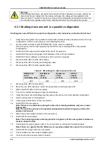
6.3.1 Shutting down one unit in a parallel configuration
Shutting down one UPS unit in a parallel configuration, with redundancy to handle the full load
1.
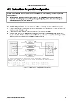
Verify that each system has 2 parallel communication cables and they are all connected in a ring
configuration. (If this is not in place you risk dropping the load)
2.
On the system controller select SYSTEM OFF on the unit to be replaced.
(This will evenly rout the load supported by the UPS to the remaining UPSs in the parallel
configuration)
3.
Switch OFF the output circuit breaker of the unit to be replaced.
4.
Switch OFF the input and bypass circuit breakers of the unit to be replaced.
5.
Switch OFF the dc (battery) circuit breaker of the unit to be replaced.
6.
Disconnect the UPS from the EPO cables.
7.
Disconnect the UPS from the Forced Bypass cable
8.
Disconnect the UPS from the parallel cables.
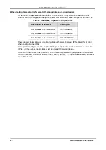
Table 9:
CB settings for safe removal of the unit
Battery box
input
(on battery box)
Rectifier ac
input
(C.B. 2)
Bypass ac
input
(C.B. 3)
UPS ac
output
(C.B. 5)
OFF
OFF
OFF
OFF
9.
Disconnect the UPS from all wiring.
10.
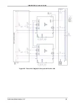
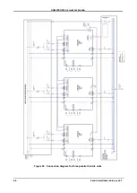
Move the new UPS into place, rewire the new system according to figure 55.
11.
Attach the EPO cable to the new system.
12.
Turn on the rectifier and bypass input circuit breakers.
13.
Verify the proper nominal settings are the same as the other units in the parallel configuration.
14.
Set the new system to "multi-system".
15.
Verity proper phase order on the new system.
16.
Switch OFF the new system.
Note: if there is a mains failure during this time the remaining batteries may have a lower
backup time.
Note: if one of the systems in the parallel configuration transfers to bypass, all the other
systems will as well.
17.
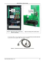
Attach the communication cables to the new system.
18.
Switch ON the new system.
Note: The remaining parallel units may transfer to bypass until the new system modules are
ready to share the load.
19.
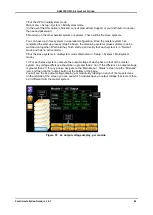
Check again for proper phase order on the new system on all input and output breakers.
Note if there is a greater than 5V difference on any phase adjust the output of each module.
20.
Switch ON the output CB of the new system.
21.
Check master and check output voltages again.
22.
Transfer all units to inverter mode if needed.

