G
AMATRONIC
E
LECTRONIC
I
NDUSTRIES
L
TD
.
CENTRIC 3x480, User Guide, rel. 1.7
113
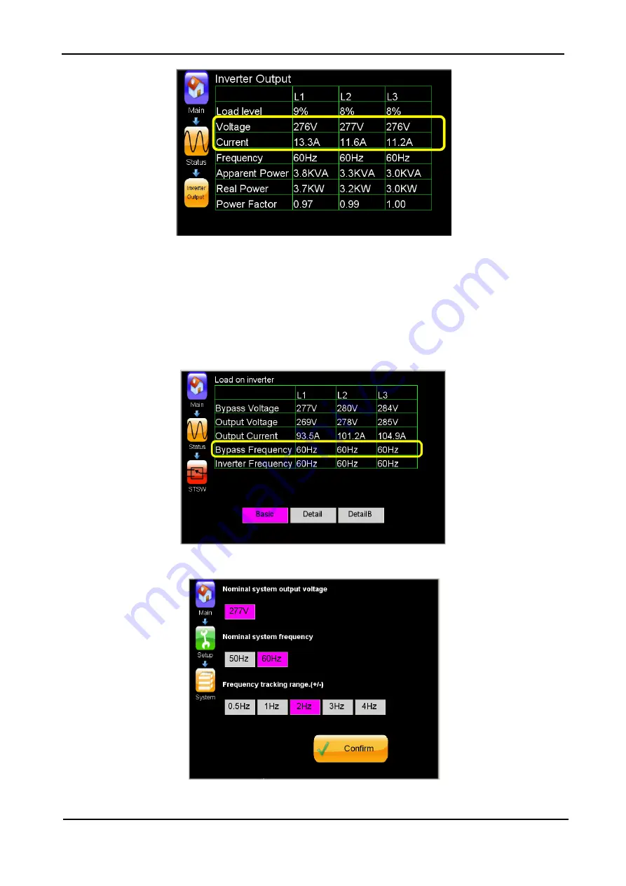
Figure 89: Voltage and current measmts. on the inverter output tab
2.
Return to the static switch measurements screen (“Status > STSW icon”). Compare the bypass
voltage measurements with the true mains power voltages. If the difference is greater than ±3 %,
perform static switch calibration.
3.
If the inverter is not synchronized to bypass, check the measured bypass frequency (Figure 90).
Verify that the setup of the nominal frequency and the frequency tracking range
(“Setup > System > Nominal settings” {Figure 91) corresponds to the actual frequency at bypass
input. Correct the setup values if necessary.
Figure 90: Bypass frequency measured at the static switch
Figure 91: “Setup nominal values” screen


