G
AMATRONIC
E
LECTRONIC
I
NDUSTRIES
L
TD
.
CENTRIC 3x480, User Guide, rel. 1.7
33
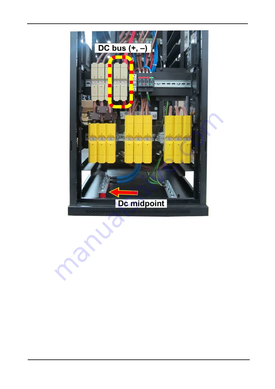
Figure 22: Measure the module’s dc voltage between the dc bus and midpoint
7.2.2.6
AC OUTPUT VOLTAGE ADJ.
Use this function to modify the voltages of the individual output phases of a specific power module. The
phase voltage can be adjusted upward or downward by up to 15 V.
7.2.2.7
DC BUS VOLTAGE CALIBRATION
This function is used to correct any inaccuracy in each module’s measurement of its internal dc voltage.
(Note: a password may be required to complete this function.) The Centric’s readings are calibrated before
the UPS leaves the factory, but over time or due to environmental factors the Centric’s dc measurements
may drift slightly.
Calibration of the dc voltage should be performed only under conditions where the UPS's input and output
currents and voltages are stable and not subject to fluctuation.
Dc voltage calibration must be performed on one module at a time, with all of the other modules turned off.
(To turn modules OFF, see section
7.3.1.3 "Operation > Switch on/off > MODULES OFF".)
The readings for the positive and negative components of the module’s dc voltage are calibrated separately
(but on the same screen), and can be increased or decreased separately.
To detect and correct any inaccuracy in the Centric’s display of the dc bus voltage:
1.
Turn off all but one module (“Main > Operation > Turn on/off”). We suggest you calibrate the modules
starting with the bottom-most module and working your way up.


