G
AMATRONIC
E
LECTRONIC
I
NDUSTRIES
L
TD
.
70
CENTRIC 3x480, User Guide, rel. 1.7
7.2.10
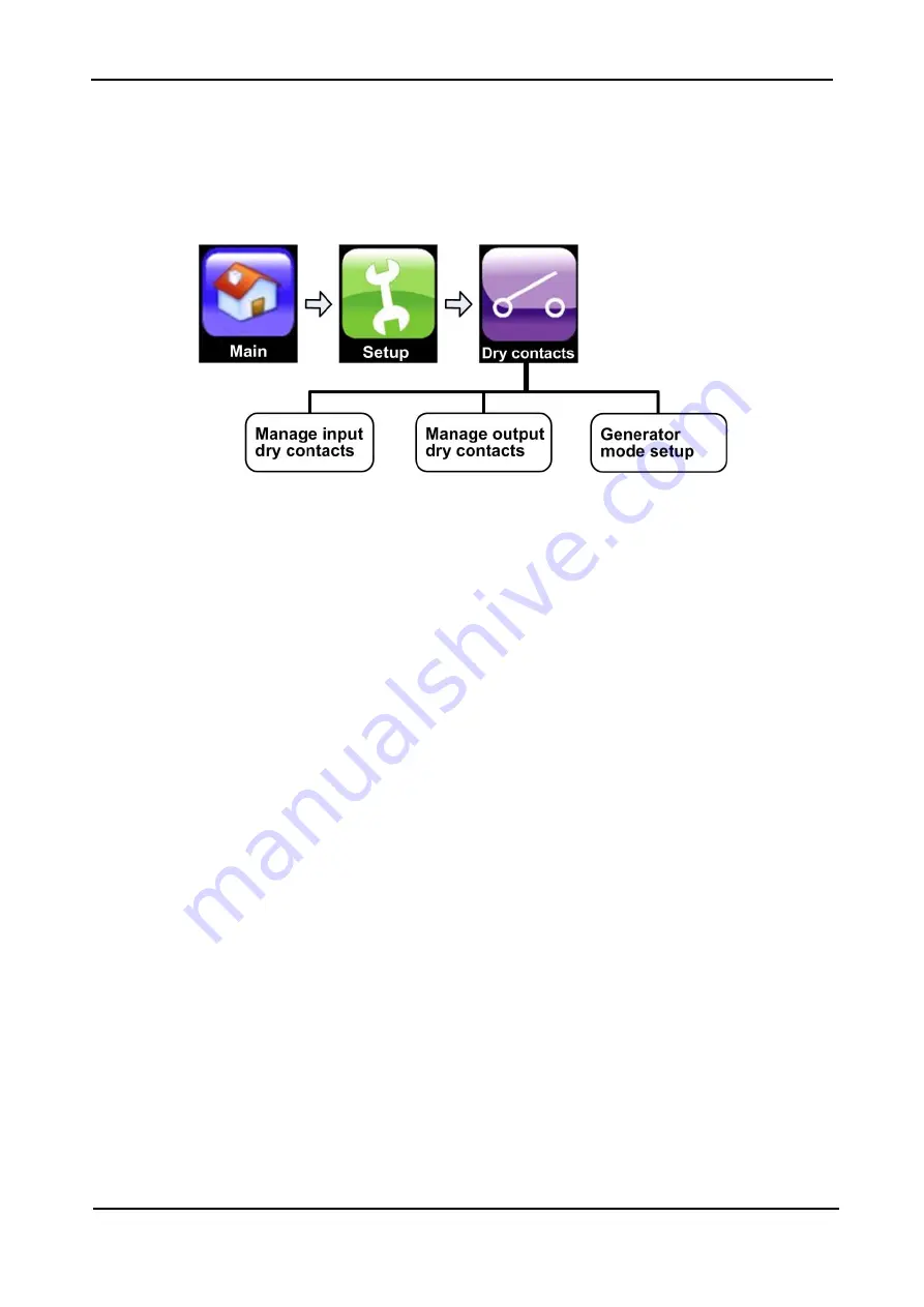
Setup > DRY CONTACTS (optional feature)
This function enables the user to manage the
Centric
's input and output dry contacts.
A password may be required to use the sub-functions on this menu. If you do not have the appropriate
password it can be obtained from your distributor or sales agent.
Figure 52: "Setup > Dry Contacts" option
7.2.10.1
SETUP > DRY CONTACTS > INPUT DRY CONTACTS
The input dry contacts enable the user to monitor the state (open or closed) of a relay external to the UPS,
by generating an alarm condition when the state of the external relay changes. (The relay must be voltage
free.
Connection of a voltage-bearing circuit or relay to the input dry contacts may damage the
Centric
.)
For example, if the battery circuit breaker has trip-indicating auxiliary contacts which close when the circuit
breaker closes and open when the circuit breaker opens, these auxiliary contacts on the battery circuit
breaker can be connected to one of the pairs of input dry contacts on the UPS, and that pair of input dry
contacts can then be programmed to generate an alarm condition when the battery circuit breaker is
opened.
7.2.10.1.1
L
OCATION OF THE INPUT DRY CONTACTS
The connections for the input dry contacts are located in two locations on the rear of the system controller.
See Chapter
The connections for four of the input dry contacts (AUX1, AUX2, AUX3, AUX4) are located in connector
group 1.
The connection for the fifth input dry contact (AUX5) consists of two pins on the D9 alarm terminal in
connector group 2.


