G
AMATRONIC
E
LECTRONIC
I
NDUSTRIES
L
TD
.
Centric 3x480 Vac, Installation Guide, rel. 2.2
39
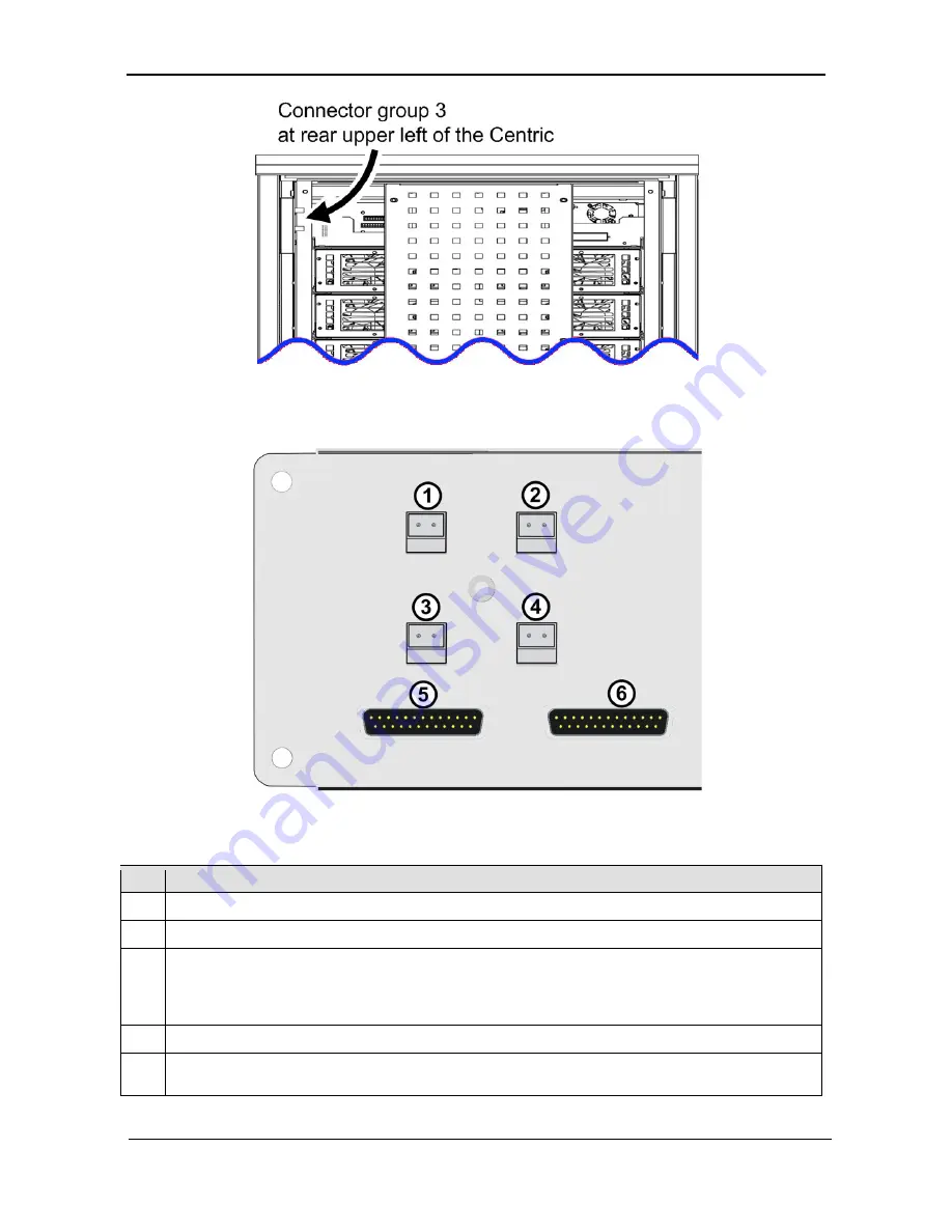
Figure 33: Location of connector group 3
Figure 34: Close-up of connector group 3
Table 10: Key to Figure 34
I
TEM
D
ESCRIPTION
1
Contacts for battery trip coil. Normally Open. See section
5.3.
2
Contacts for Emergency Power-Off (EPO) switch. Normally Open. See section
5.2.
3
Forced Bypass contacts. Normally Open. When these contacts are closed, the UPS immediately
goes into bypass mode. These contacts are intended to be used in conjunction with the
Maintenance Bypass function. They should be closed by the user’s maintenance bypass switch, to
ensure that the UPS is in bypass mode before moving to maintenance bypass model.
4
Load on bypass contacts. Normally Open. See section
5.4.
5, 6
Connections for the two parallel communication cables when two or more Centric 480 UPS’s are
being operated in parallel configuration.


