G
AMATRONIC
E
LECTRONIC
I
NDUSTRIES
L
TD
.
12
CENTRIC 3x480, User Guide, rel. 1.7
4.2
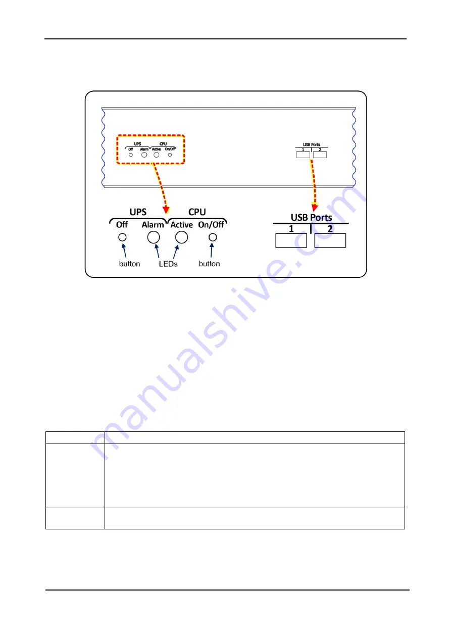
Buttons and LEDs on the system controller
On the system controller, to the left of the LCD touch screen are two buttons, and two LEDs. These are
described below.
Figure 6: The Centric’s top front panel
4.2.1
“UPS off” button
Pressing the ‘UPS off” button for ten seconds turns the Centric OFF.
This button is intended for use only when the LCD screen is not functional. Under normal circumstances
the on/off button icon in the upper right corner of the touch screen should be used to switch off the UPS.
Note: disabling the controller self-shutdown function (watchdog function) also disables the
“UPS OFF” button
. See section
7.2.1.6.3 for more information.
4.2.2
“Alarm” LED
The “Alarm” LED lights when there is an alarm situation present. This LED is the physical counterpart of the
software generated triangular “alarm” indicator on the LCD panel’s main screen.
The Alarm LED has 3 possible states:
Off (unlit)
There are no active system alarms.
Blinking red
There are one or more active alarms of status “Warning” or “Error”. To see a list of the
active alarms, press the alarm icon on the main screen. The icon will be either
•
a red circle with an “x” in the middle (when the most serious active alarm is of
“error” status) or
•
a yellow triangle with an exclamation point inside, when the most serious active
alarm is of “warning” status.
Solid red
There are active alarms, but you have listed them already on the LCD screen. When a
fresh alarm occurs, the Alarm LED will start blinking again.
For more information on system alarms, see “Alarm indicator” in Table 6, and refer to
chapter


