G
AMATRONIC
E
LECTRONIC
I
NDUSTRIES
L
TD
.
Centric Installation Guide, rel. 2.8
33
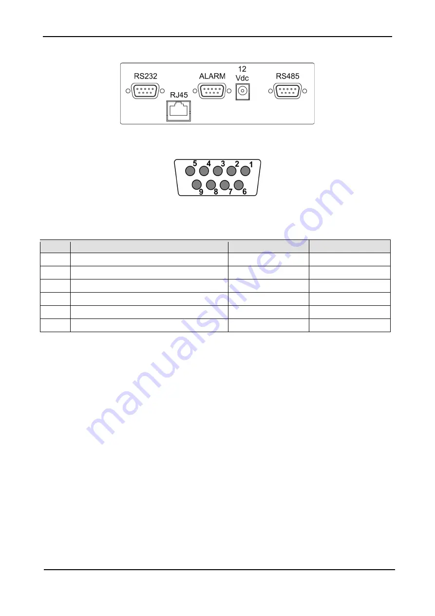
Figure 26: Close-up of connector group 2
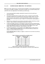
Figure 27: Pin numbers in D9 connectors
Table 6: D9 pin assignments in connector group 2
P
IN
#
ALARM
CONNECTOR
RS232
CONNECTOR
RS485
CONNECTOR
1
Input dry contact #5 (AUX5)
RXD, Receive data
RTX-
2
Reserved
TXD, Transmit data
not used
3
Line failure (default; can be reassigned)
not used
RTX+
4
COMMON
GND
not used
5
Low battery (default; can be reassigned)
not used
not used
6-9
Remote panel
not used
not used


