G
AMATRONIC
E
LECTRONIC
I
NDUSTRIES
L
TD
.
Centric Installation Guide, rel. 2.8
40
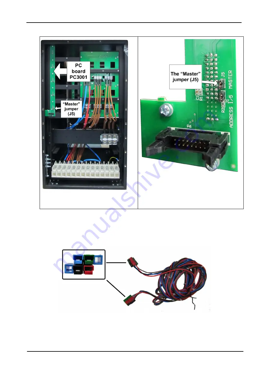
Figure 34: Rear of the Centric, showing the
PC3001 circuit board
Figure 35: Closeup of the master jumper
4.
The parallel UPSs must be connected to one another via their
current sharing terminals
28), using the current sharing cable supplied in the cable kit (see Table 7 above). The kit includes
cables for current sharing between two, three or four Centric units in parallel.
Figure 36: Current-sharing cable


