G
AMATRONIC
E
LECTRONIC
I
NDUSTRIES
L
TD
.
Centric Installation Guide, rel. 2.8
20
3.2.4.5
ASSEMBLING AND CONNECTING THE BATTERIES
Note: The Centric supports the use of standard lead-acid batteries, and also lithium-ion batteries.
If you plan to use lithium-ion batteries, consult with your dealer to be sure that the battery setup
parameter values are appropriate for the batteries you will be using.
1.
It is recommended that the battery cabinet(s) be located as close to the UPS as is
practically possible.
2.
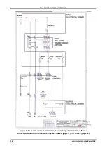
Assemble the batteries within the battery cabinet. Figure 12 shows the recommended
connection method, which includes two fuses inside of each battery cabinet, one on the
plus line and one on the minus line. The recommended fuse values for one set of two
cabinets of 30 x 12 Vdc each are shown in Figure 12, according to the output capacity of
the UPS.
3.
Measure the dc voltage at the main terminals of the battery cabinet. Verify that you obtain
values of +360 Vdc (red) and –360 (black) with reference to N (blue).
4.
Connect each battery cabinet to a circuit breaker or switch with fuses according to Figure
12. The recommended fuse value for two battery cabinets is shown in Figure 12, according
to the output capacity of the UPS. The two switches or circuit breakers (one for each
battery cabinet) should be located as close as possible to the UPS.
5.
Connect the two switches or circuit breakers to the
Centric
battery terminals. Refer to
Observe proper polarity!
Minimum recommended cable size between the
battery box and the UPS is shown in Table 4
For the 200 kVA model
, the battery’s “midpoint” connection is to the Centric’s neutral bus
bar (see Figure 5.)
Table 4: Minimum recommended size of battery cables*
UPS Power
(kVA)
Minimum cable
size (mm
2
)
50
16
75
35
100
50
125
70
150
95
175
120
200
150
* Values are for 10 min. backup time,
and are based on IEC6950 Table 3B and NEC Table 310.16.
For longer backup times please consult Gamatronic’s customer service department.


