GAMATRONIC,
A
S
OLAR
E
DGE
D
IVISION
Centric Installation Guide, rel. 4.7
59
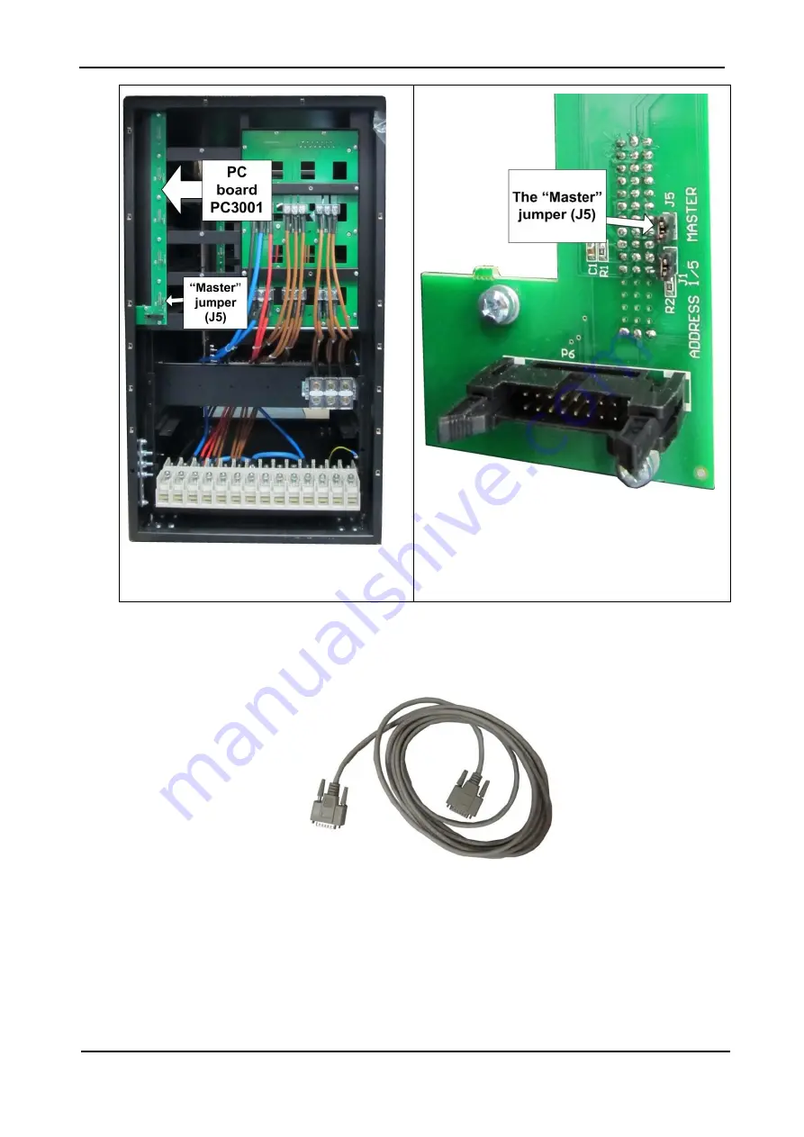
Figure 47: Rear of the Centric, showing the
PC3001 circuit board
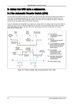
Figure 48: Closeup of the master jumper
4.Connect the UPSs in a ring configuration via the two 15-pin
parallel communication terminals
on each UPS. Use the supplied cables. See Figure 21, Figure 25
Figure 49: Parallel communication cable with 15-pin connectors


