GAMATRONIC,
A
S
OLAR
E
DGE
D
IVISION
Centric Installation Guide, rel. 4.7
68
6.3.3 Returning the UPS back to normal mode from maintenance
bypass mode
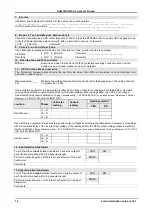
Table 11: Maintenance Bypass Mode CB Configuration
Battery box
input
(on battery box)
Rectifier ac
input
(C.B. 2)
Bypass ac
input
(C.B. 3)
UPS AC
output
(C.B. 5)
Maintenance bypass
(C.B. 6)
OFF
OFF
OFF
OFF
ON
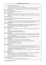
To put the system in normal mode (inverter mode), perform the
following operations:
In maintenance bypass operation, the UPS's ac circuit breakers are positioned as shown in
(see Figure 1 for C.B. locations).
1.
Switch ON the RECTIFIER AC INPUT circuit breaker.
2.
Switch ON the BATTERY circuit breaker.
3.
Switch ON the BYPASS AC INPUT circuit breaker.
4.
Switch ON the UPS (Operation>system on). Wait for the system to automatically transfer to inverter
once all the power modules are operational.
5.
On the system controller LCD screen press operations> transfer load to bypass.
6.
Verify that the bypass indicator is lit on the controller.
7.
Switch ON the AC OUTPUT circuit breaker.
8.
Switch OFF the MAINTENANCE BYPASS circuit breaker.
9.
On the system controller LCD screen press operations> transfer load to inverter.
10.
Verify that the load is being supported by the inverters on the Status screen.
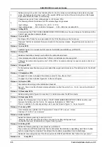
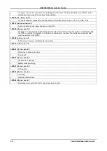
The switches are now positioned as shown in Table
Table
12: Position of the CBs in normal mode
Battery box
input
(on battery box)
Rectifier ac
input
(C.B. 2)
Bypass ac
input
(C.B. 3)
UPS ac
output
(C.B. 5)
Maintenance bypass
(C.B. 6)
ON
ON
ON
ON
OFF
The system is now in normal mode (inverter mode) and is now supporting the load.


