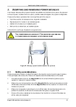
G
AMATRONIC
E
LECTRONIC
I
NDUSTRIES
L
TD
.
MegaV2 250 Installation Guide, Release 2.2
28
2.2
First-time insertion of power modules at system
installation
When the installation instructions in section 1.2 call for it, insert the power modules into the
module shelf. For each module:
1
.
Before inserting the power module, verify that the two circuit breakers on the module's rear
panel are in the OFF (down) position.
2
.
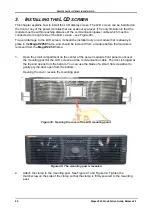
Two persons are required to lift the module and slide it into the shelf. One person shall
stand on each side of the shelf (Figure 25). There is a pin on each side of the power
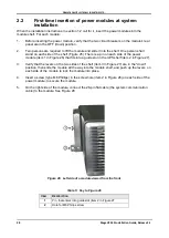
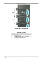
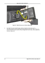
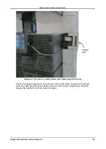
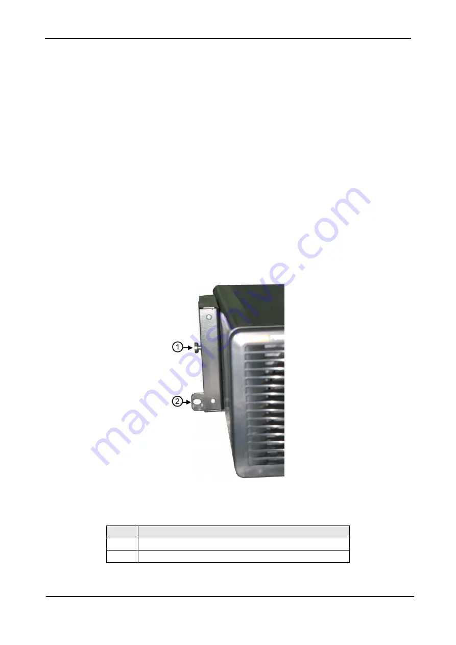
module (item 1 in Figure 26) that fits into a guide slot in the UPS shelf (item 2 in Figure 27),
3
.
Verify that the levers on the two sides of the shelf (item 3 in Figure 27) are in the "down"
position, then slide the module all the way into the module shelf, and push up the levers on
each side of the module to lock the module into place.
4
.
Insert a screw (type M6 Phillips) in the screw hole (item 2 in Figure 26) on each side of the
power module, to secure the module.
5
.
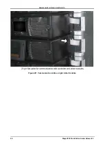
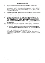
On the right side of the module, connect the 26-pin flat cable (the system communication
cable) to the module. See Figure 28.
.
Figure 26: Left side of a module viewed from the front
Table 5: Key to Figure 26
I
TEM
D
ESCRIPTION
1
Pin that enters into guide slot (item 2 in Figure 27.
2
Hole for M6 Philips screw

