Gamatronic Electronic Industries Ltd.
User Guide: MEGA V2 SA25, Release 1.5
35
3.
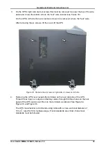
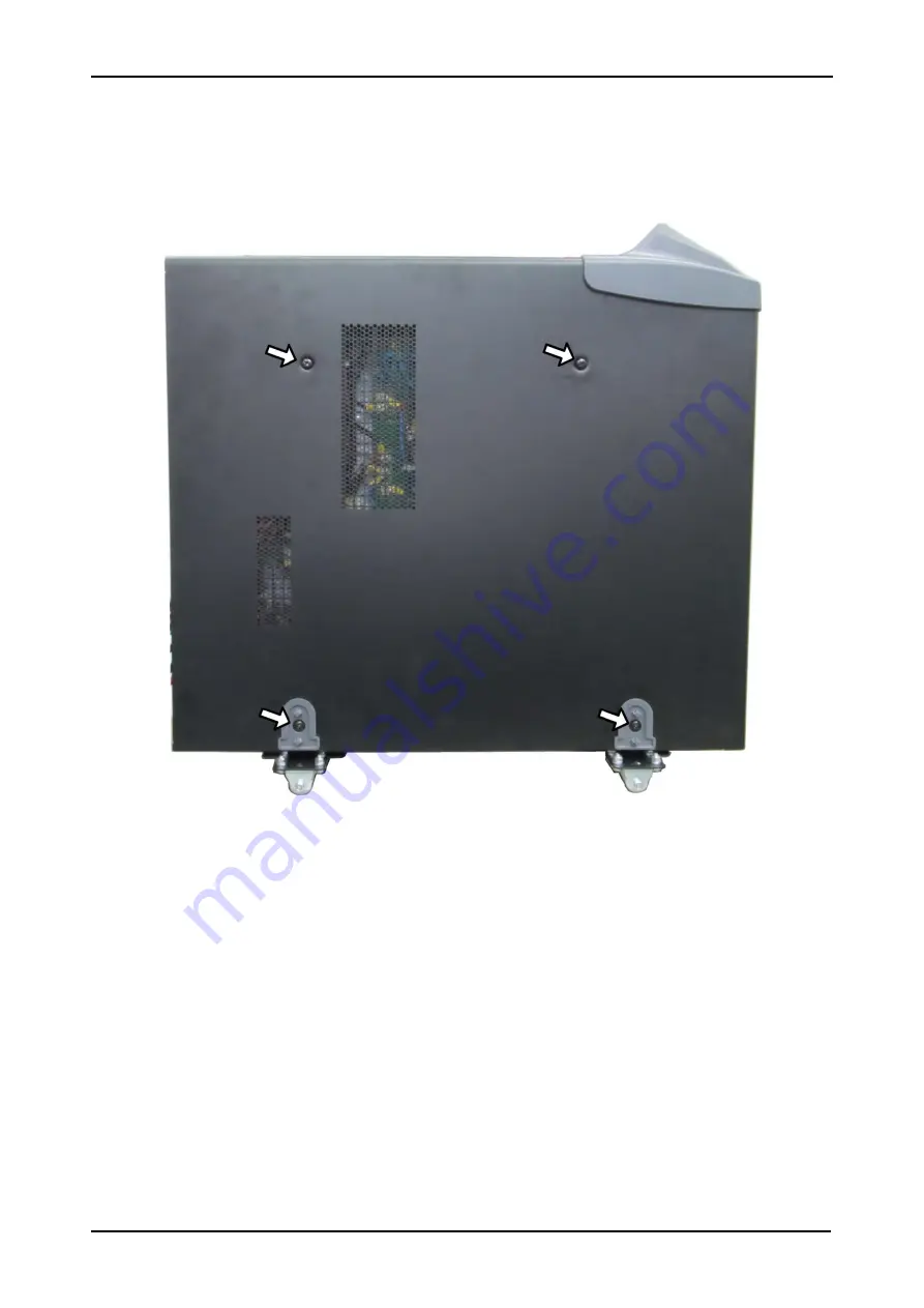
On the UPS’s right side are four screws that must be removed: two near the top of the side
panel and 2 near the bottom, where the “feet” were located (see Figure 33).
On the UPS’s left side there are just two screws to be removed, where the “feet” were.
After removing the six screws, lift the cover off the UPS
Figure 33: Remove the 4 screws on right side, 2 screws on left side
4.
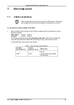
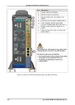
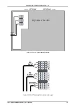
Removing the UPS cover reveals the terminals on the rear right side of the UPS.
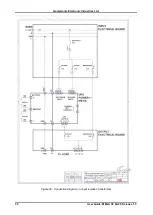
Thread the ac input, ac output, and battery cables through the three holes on the rear
panel of the UPS and connect them to the terminals, as labeled. See Figure 34,
Figure 35, and Figure 36.
The UPS manufacturer recommends using cable with a cross-sectional diameter of
10 mm
2
, rated for 50 A 3-phase usage. If local standards are stricter, those local
standards must be followed.

