background image


P+ Premium SA, 15 kVA, rel. 1.4 


2.3


Bypass Mode 

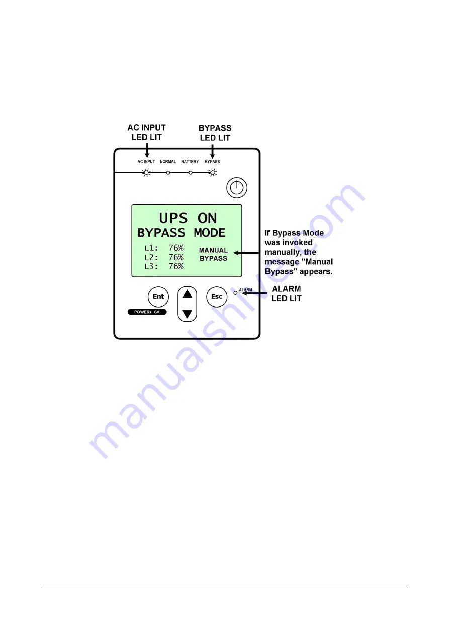
In bypass mode the load receives power directly from the ac input via the static switch. 

Whenever the inverters cannot provide power to the load, for example, due to an overload or a short-circuit 
in the load, the UPS supplies the load directly from the ac input, bypassing the inverter. As soon as the 
problem is corrected, the load is transferred back to the inverter automatically.  


Bypass Mode display 

Summary of Contents for POWER Plus Premium SA 15

Page 1: ...2 2 582 8875 Email info gamatronic co il Website www gamatronic com 2MUM PR SA POWER Premium SA 15 1 15 5 K KW W D DO OU UB BL LE E C CO ON NV VE ER RS SI IO ON N U UP PS S W WI IT TH H T TR RU UE E O...

Page 2: ...e for any damage or malfunction due to incorrect wiring of the batteries Gamatronic is not liable for and the Purchaser waives any right of action it has or may have against Gamatronic for any consequ...

Page 3: ...ections 32 7 1 1 Cable connections for unit with NO manual bypass 33 7 1 2 Cable connections for UPS WITH manual bypass 36 7 2 Installation and Start Up Sequence 39 7 2 1 To start the UPS 39 7 2 2 Ver...

Page 4: ...2 LIST OF FIGURES Figure 1 The POWER PREMIUM SA 15 2 Figure 2 Block diagram of the POWER PREMIUM SA 15 3 Figure 3 Connections at the rear of the UPS 35 Figure 4 UPS rear panel with protective cover 37...

Page 5: ...GAMATRONIC ELECTRONIC INDUSTRIES LTD P Premium SA 15 kVA rel 1 4 v v ATTACHING THE POWER PREMIUM SA TO ITS BASE Attaching the POWER Premium Stand Alone to its base...

Page 6: ...ace between the ventilation openings of the UPS and other objects or walls The UPS must be well grounded to the building s grounding system with a conductor that has a current carrying capacity that m...

Page 7: ...ect or disconnect the cable to the battery cabinet before the battery circuit breaker is turned OFF Do not turn ON the battery circuit breaker when the battery cabinet is disconnected from the UPS Do...

Page 8: ...grams which include images of the UPS and of its LCD display screen Unless otherwise indicated these images are representational only and are not intended to match the exact appearance of a particular...

Page 9: ...s The efficiency of POWER PREMIUM SA 15 thus helps to extend the life of your equipment even during normal use when the input power is constant and continuous POWER PREMIUM SA 15 IS UNIQUE BECAUSE IT...

Page 10: ...SA 15 CONTROL PANEL The POWER PREMIUM SA 15 control panel allows the user to manage and control the POWER PREMIUM SA 15 monitor the parameters of all sections of the POWER PREMIUM SA 15 CHARGER The U...

Page 11: ...no longer supply power to the load The static switch transfers current at high speed BATTERY The POWER PREMIUM SA 15 battery bank is used as a backup in the event that the utility ac input fails The b...

Page 12: ...ic modes of operation Normal mode Battery mode Bypass mode 2 1 Normal Mode POWER PREMIUM SA 15 almost always operates in normal mode In normal mode the load receives its power from the inverters that...

Page 13: ...to receive power from the inverters but the dc input to the inverter is taken from the batteries instead of from the rectifier The batteries are galvanically connected by dc link to the inverter and...

Page 14: ...tatic switch Whenever the inverters cannot provide power to the load for example due to an overload or a short circuit in the load the UPS supplies the load directly from the ac input bypassing the in...

Page 15: ...l Panel The POWER PREMIUM SA 15 Control Panel includes an LCD display control buttons and LED indicators The control panel has three principle functions Shows the current operating mode Lets you displ...

Page 16: ...n Screen silences the audible alarm 3 1 3 Indicators The top of the control panel contains four LCD indicators The status indicators show what is running and how the UPS is providing power to the load...

Page 17: ...used for 45 seconds the POWER PREMIUM SA 15 returns to the Main Screen The Main Screen shows the UPS s current operating mode and other critical data Other screens describing current operating condit...

Page 18: ...N NORMAL MODE The ac INPUT and NORMAL LEDs are lit The following picture shows the Main Screen as you will see it most of the time in Normal Mode In the event of a battery test failure an icon indicat...

Page 19: ...ONIC INDUSTRIES LTD P Premium SA 15 kVA rel 1 4 11 In the event of an overload condition an icon indicating this appears in the lower right quadrant of the Main Screen the alarm LED ligits and the aud...

Page 20: ...5 kVA rel 1 4 3 2 1 2 BATTERY MODE When the UPS is operating in battery mode the Main Screen first displays the message UPS ON BATTERY MODE As the battery discharges the number of stripes on the batte...

Page 21: ...time save your data and perform an orderly shutdown of any computers connected to the UPS if you have not already done so When the UPS battery is exhausted the UPS does one of two things depending on...

Page 22: ...14 P Premium SA 15 kVA rel 1 4 When auto restart is ENABLED the Main Screen shows the UPS ON message When ac power is restored the UPS starts up automatically...

Page 23: ...goes into bypass mode automatically in the case of an overload or if there is an inverter fault Bypass mode can also be invoked manually If the UPS was put in Bypass mode manually the message Manual B...

Page 24: ...F mode is invoked by pressing the On Off button twice when the UPS is operating The OFF screen displays the message UPS OFF NO OUTPUT OFF mode can also be invoked automatically in the event of an exte...

Page 25: ...GAMATRONIC ELECTRONIC INDUSTRIES LTD P Premium SA 15 kVA rel 1 4 17 OFF mode can also be invoked remotely through the RS232 data connection...

Page 26: ...lock HH MM SS See section 8 1 for instructions on setting the system clock Nominal output voltage Nominal output frequency Auto restart status ON or OFF See chapter 9 for information about the Auto Re...

Page 27: ...en 3 3 2 2 2 AC OUTPUT SCREEN To see the current status of the UPS s ac output from the Main Screen press twice The checkmark indicates that the ac voltage of each output phase is within acceptable ra...

Page 28: ...d instead of the checkmark The voltage and current for the three input phases is displayed 3 2 2 4 BYPASS SCREEN To see the current status of the Bypass from the Main Screen press four times The check...

Page 29: ...inverter output is phase synchronized with the bypass input SYNC ORD The phase sequence of the bypass input is incorrect SYNC FLT The bypass input and the inverter output are not in sync A checkmark...

Page 30: ...e the current battery status and voltages from the Main Screen press six times The battery status can be BATTERY OK BATTERY LOW or BATTERY FLT means the battery failed the latest battery test The batt...

Page 31: ...ures To display the Main Menu from the Main Screen press Ent POWER PREMIUM SA 15 Main Menu The Main Menu options are described elsewhere in this book Event Log The event log displays current alarm con...

Page 32: ...beginning the process from the UPS OFF NO OUTPUT screen 1 Press the ON OFF button twice The BYPASS and ALARM LEDs light up for about 40 seconds 2 After a short time the screen reads UPS ON NORMAL MODE...

Page 33: ...o shut it down for a period of time during which the load devices will not be operating Begin the process from the UPS ON NORMAL MODE screen 1 It is advisable to turn of all equipment connected to the...

Page 34: ...vigating to the event log To see the event log 1 From the Main Screen press the Ent button to display the Main Menu 2 On the Main Menu press Ent again 5 2 1 Active Alarm display The first thing you se...

Page 35: ...eginning of the file so that the oldest events in the log are overwritten by the newest events The illustration shows a typical log entry The first line gives the number of the log entry This is the 2...

Page 36: ...UPS this may resolve the problem If not contact Technical Support BATTERY LOW Meaning The battery will soon be fully discharged Additional indications The alarm LED lights up and the audible alarm so...

Page 37: ...ts up and the audible alarm sounds The symbol appears on the Inverter screen Action Contact Customer Support LOAD ON BYPASS Meaning The output voltage is the Bypass voltage Additional indications Acti...

Page 38: ...iled battery test END OF BACKUP Battery has been completely discharged RECHARGING Mains power has returned and battery is recharging INVERTER OFF The inverter has been turned off INVERTER ON The inver...

Page 39: ...t button to display the Main Menu On the Main Menu select Battery Test and press Ent The resulting screen tells you the time until the next scheduled automatic battery test To perform a manual test pr...

Page 40: ...htly depending on whether or not your UPS includes a manual bypass switch ich line configuration is used Refer to the appropriate section below The cable connections on your unit may have a slightly d...

Page 41: ...power connections on your own To connect the required cables to the UPS for 3 3 usage 1 Use cables appropriate for the currents shown in Table 3 according to your local electrical codes 2 Ensure that...

Page 42: ...is shown in the next illustration 4 Unplug the green plastic connectors and wire them as labelled Be sure the wires are not live before you begin Use wires of the proper diameter for the currents sho...

Page 43: ...at the rear of the UPS 5 Connect the wired connectors to the rear of the UPS 6 Use the supplied battery cable to connect the battery to the UPS 7 Recheck the connections before continuing 8 To concea...

Page 44: ...re it for initial start up 1 Verify that the external circuit breaker in the mains electrical cabinet for UPS input is OFF No voltage should be present in the cables 2 Verify that the battery cabinet...

Page 45: ...Premium SA 15 kVA rel 1 4 37 Figure 4 UPS rear panel with protective cover Note the Manual Bypass Switch is OPTIONAL EQUIPMENT not standard If the customer desires a Manual Bypass Switch it must be s...

Page 46: ...beled ac input in Figure 5 Connect the cable to the ac input terminals also shown in Figure 5 Use the appropriate grade of wire as specified in Table 4 on page 36 or according to local electrical code...

Page 47: ...A 15 kVA rel 1 4 39 Figure 6 Additional views of the UPS rear panel 7 2 Installation and Start Up Sequence 7 2 1 To start the UPS 1 Attach the load device if desired but do not turn it on until you ha...

Page 48: ...quirements The phase setting can be seen on the second page of the Profile screen shown here with the phase setting highlighted See page 18 for instructions on how to display the Profile screen 7 2 3...

Page 49: ...art mode at this time if desired See Automatic Restart on page 45 7 2 7 Operation To turn the UPS on press the ON OFF button twice and wait a few seconds The following screen is displayed The AC Input...

Page 50: ...changes you made before pressing Esc are saved 4 The SET MINUTES screen is displayed Use the UP DOWN button to change the minutes setting 5 Press Ent The SET HOUR screen is displayed Use the UP DOWN b...

Page 51: ...urn the UPS off 2 From the Main Screen press the Ent button to display the Main Menu 3 On the Main Menu choose ADVANCED OPTIONS and press Ent 4 In the ADVANCED MENU select TECHNICIAN MENU 5 In the TEC...

Page 52: ...NCED OPTIONS and press Ent 3 In the ADVANCED MENU select TECHNICIAN MENU 4 In the TECHNICIAN MENU select CHANGE VOLTAGE 5 You are prompted to choose the type of voltage to change Select OUTPUT VOLTAGE...

Page 53: ...he AC power returns the recharging process begins automatically but no power is supplied to the load 9 1 Determining the current automatic restart setting To determine if the automatic restart mode is...

Page 54: ...46 P Premium SA 15 kVA rel 1 4 5 The new automatic restart status is displayed Press Esc to return to the Main Screen...

Page 55: ...itch the UPS to Bypass mode THERE ARE TWO WAYS TO MANUALLY ENTER OR LEAVE BYPASS MODE Using the manual bypass switch on the UPS rear panel Using the system console 10 1 1 Entering bypass mode via the...

Page 56: ...een press the Ent button to display the Main Menu 2 On the MAIN MENU select ADVANCED MENU and press Ent 3 On the ADVANCED MENU select TRANSFER LOAD and press Ent The TRANSFER LOAD screen tells you if...

Page 57: ...GAMATRONIC ELECTRONIC INDUSTRIES LTD P Premium SA 15 kVA rel 1 4 49 On the Main Screen the message Manual Bypass appears in the lower right quadrant The audible alarm sounds after 60 seconds...

Page 58: ...ccurs The Alarm LED lights up and the audible alarm sounds The UPS continues operating drawing its power from the batteries The POWER SA console looks like this The Alarm and Battery LEDs are lit As t...

Page 59: ...e time to shut down any computers connected to the UPS if you have not already done so When the UPS battery is exhausted the UPS does one of two things depending on the setting of Auto restart mode If...

Page 60: ...52 P Premium SA 15 kVA rel 1 4 If Auto restart is ENABLED the Main Screen shows the UPS ON message When AC power is restored the UPS starts up automatically...

Page 61: ...al circuit breaker for the AC line The circuit breaker may be off 12 3 Battery Test failed It may be that an automatically scheduled battery test was executed shortly after the end of a power outage w...

Page 62: ...54 P Premium SA 15 kVA rel 1 4 Figure 8 Block diagram of major components and connections...

Page 63: ...REMIUM SA 15 UPS system The dry contact circuits make use of opto couplers No more than 30V and 100mA should be applied to a dry contact The Alarm Dry Contacts can report any of three conditions as de...

Page 64: ...56 P Premium SA 15 kVA rel 1 4 The following figure is a schematic of the Dry Alarm Contacts The triangles represent pins the numerals in the triangles represent pin numbers...

Page 65: ...s well There are two types of UPS connections Directly to a host computer with dedicated software Remote control through a SNMP WEB management programs for communication with a computer network option...

Page 66: ...The SNMP agent communicates with the RS232 interface of the UPS which Supports standard UPS RFC1628 MIB Supports the SNMP commands Trap Set and Get Transfers UPS indicators such as voltage frequency a...

Page 67: ...tronic WING The WING enables real time detection of power system faults and immediately notifies selected recipients control center technician etc detailing the faults The WING includes the following...

Page 68: ...no liability for damage caused to the UPS due to improper maintenance by third parties in particular after the expiration of the warrantee or service agreement It is the responsibility of the UPS owne...

Page 69: ...Dc Ac efficiency Up to 98 Static Switch Input connection Dual input General Maximum power dissipation Po 15 kW 625 W 2133 BTU hr Ambient temperature C 10 to 40 operating 20 to 60 storage Relative hum...

Page 70: ...62 P Premium SA 15 kVA rel 1 4 20 FLOWCHART OF SYSTEM FUNCTIONS Figure 9 Flowchart of system functions...

Page 71: ...industry Dc to ac inverters Dc to dc converters Frequency converters Battery chargers Power management solutions Headquarters and Factory 17 Hartum Street Har Hotzvim Industrial Park POB 45029 Jerusal...

Reviews: