36
P+ Premium SA, 15 kVA, rel. 1.4
7.1.2
Cable connections for UPS WITH manual bypass
Note: the Manual Bypass Switch is OPTIONAL EQUIPMENT, not standard. If the customer desires a
Manual Bypass Switch it must be specifically ordered as a separate item.
This section describes cable connections for using the POWER+ PREMIUM SA 15 in 3-3
configuration using the rear-panel adapter that
HAS A MANUAL BYPASS SWITCH
.
The rear panel adaptor provides “single-feed” input, meaning that the bypass input is taken from the
rectifier input lines.
For 3-3 connections for the adapter
without
a manual bypass switch, see section
To install the UPS and prepare it for initial start-up:
1.
Verify that the external circuit breaker in the mains electrical cabinet for
UPS input
is
OFF
. No voltage
should be present in the cables.
2.
Verify that the
battery cabinet
circuit breaker is
OFF
.
3.
Use cables appropriate for the currents shown in Table 4 according to your local electrical codes.
4.
Ensure that the UPS’s input and output cables are equpped with circuit breakers appropriate for the
chosen cables.
Table 4: Wiring requirements for system w/ manual bypass sw.
AC output
(Gnd, N, L1, L2, L3)
AC and bypass
input
(Gnd, N, L1, L2, L3)
Battery input
3 x 21.7 A
3 x 27 A
A cable of 4 mm
2
cross-sectional
area is required. (Use the 1.5
meter-long battery cable supplied
by Gamatronic.)
5.
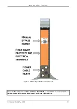
Remove the protective cover from the UPS rear panel.
6.
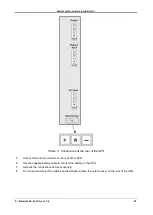
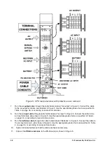
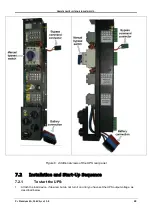
Connect the UPS wiring according to the labeling on the unit, shown in Figure 5 on page 38.


