Gamatronic Electronic Industries Ltd.
Power+ Technical Guide
87
11.3
ADDING A POWER MODULE
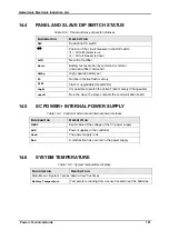
If an additional shelf is attached at the top of the system, the DIP switch of the Control PCB
must be changed to the next address code as shown in Table
Updating the number of modules in the Power Plus processor:
(‘Ent’ represents a press of the
Ent
key.)
Ent,
Setup
,
Ent,
Password
(default password is 8 “left arrows” [
½
] ),
Ent,
Service
,
Ent,
Configure
Ent,
Total # of UPS
,
Ent,
(enter number of UPSs)
,
Ent , Ent
The system reinititializes itself.
11.3.1.1 T
URNING OFF THE OUTPUT CURRENT LIMIT
:
Ent,
Setup
,
Ent,
Password
(default password is 8 “left arrows” [
½
] ),
Ent,
Battery
,
Ent
, Current Limit
,
Ent,
Enable current limit (off)
Esc.


