G
AMATRONIC
E
LECTRONIC
I
NDUSTRIES
L
TD
.
16
Power+ PREMIUM, Installation Guide, rel.
1.7
2.4.1
Load on bypass alarm
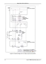
This output dry contact is Normally Open, and closes when the UPS transfers the load to bypass (Figure
). The dry contact reopens again when the UPS returns to inverter mode.
2.4.2
Battery trip coil
The battery trip coil terminals are intended to be connected to the trip coil of the battery circuit breaker
(Figure
). If this is done and the EPO switch is activated, the P
OWER
+ sends a pulse of 120 V to the
battery circuit breaker trip coil, causing the battery circuit breaker to turn OFF.
Use of the battery trip coil means that not only will use of the EPO switch cut all ac output from the UPS, it
will also turn off the battery circuit breaker.
2.4.3
Emergency power-off
An external Emergency Power-Off (EPO) switch can be installed by the customer to enable immediate
shutdown of the UPS. Once switched off by the EPO, the POWER+ must be restarted manually.
The UPS has two terminals marked "EPO" for connection of an EPO switch (Figure
). Use of a large
mushroom-type N.O. (normally open) pushbutton rated for not less than 1 A / 24 Vdc is recommended.
Verify continuity of the switch at its connection points before installing.
In the event that the POWER+ UPS is used in a computer room
, installation of the EPO switch is
mandatory. It is also
required
in this case that activating the EPO switch should disconnect the dc power
supply from the batteries. The battery CB terminals on the POWER+ must be connected to the trip coil
terminals on the battery cabinet (see section 2.4.2).
To restart the UPS following use of the EPO, turn off all input circuit breakers (rectifier ac input, bypass ac
input, battery) and then start the Power+ Premium as normal
(Main Menu > Operation > Turn On/Off > System On).


