background image

Gamatronic Electronic Industries Ltd.

POWER+


SA

 User Guide, Release 1.6 


      31 


LOG MESSAGES


Log Entry 

Explanation 

AC LINE FAULT 

No input voltage to charger. 

AC LINE OK 

Input voltage to charger has been restored 

BATT. TEST FAIL 

The last battery test failed.  

BATT. TEST.OK 

The last battery test was successful (following a failed battery 
test). 

END OF BACKUP 

Battery has been completely discharged.  

RECHARGING 

Mains power has returned and battery is recharging. 

INVERTER OFF 

The inverter has been turned off. 

INVERTER ON 

The inverter has been turned on. 

OVERLOAD 

An overload condition exists. 

LOAD IN RANGE 

The load has returned to normal range. 

LOAD ON BYPASS 

The load is bypassing the inverter. 

LOAD ON INVERTER 

The load has returned to the inverter. 

UPS OFF 

The UPS was turned off. 

UPS ON 

The UPS was turned on. 


Summary of Contents for power+ sa

Page 1: ...SA 1 10 0 K KV VA A D DO OU UB BL LE E C CO ON NV VE ER RS SI IO ON N U UP PS S T TR RU UE E O ON N L LI IN NE E B BA AT TT TE ER RY Y User configurable input and output voltage options I IN NP PU UT...

Page 2: ...Ltd reserves the right without prior notice or liability to make changes in equipment design or specifications Information supplied by Gamatronic Electronic Industries Ltd is believed to be accurate...

Page 3: ...UPS Off 17 Status Screens 19 UPS Profile screens 19 AC Output screen 20 AC Input screen 21 Bypass screen 21 Inverter SCREEN 22 Battery SCREEN 23 The Power SA Main Menu 24 4 DAILY OPERATION 25 POWER S...

Page 4: ...omatic restart setting 50 Changing the automatic restart status 50 10 MISCELLANEOUS FUNCTIONS 52 Manually entering or leaving Bypass Mode 52 11 IN THE EVENT OF AN AC POWER OUTAGE 54 12 TROUBLESHOOTING...

Page 5: ...or current will show data for one or three phases depending on the unit s current operating parameters The figures below show the UPS Main screen displaying output voltages in 3 phase and in 1 phase...

Page 6: ...Gamatronic Electronic Industries Ltd vi POWER SA User Guide Release 1 6 ATTACHING THE POWER SA TO ITS BASE Attaching the POWER Stand Alone to its base...

Page 7: ...and free from excess moisture Allow only qualified technicians to service the UPS There are no user serviceable components Do not try to repair it yourself Use the UPS only for its intended purpose WA...

Page 8: ...RNING RISK OF SEVERE DAMAGE TO THE UPS THIS SYSTEM USES THE NEUTRAL LINE FOR OPERATION THEREFORE IT IS STRICTLY FORBIDDEN TO CONNECT THIS SYSTEM TO THE AC POWER SOURCE WITHOUT A NEUTRAL NULL CONDUCTOR...

Page 9: ...of your equipment even during normal use when the input power is constant and continuous POWER SA is unique because it Is a true on line battery design according to IEC 62040 31 Is a green power solut...

Page 10: ...rated reactive power Reactive power operates at right angles to true power and energizes the magnetic field Reactive power has no real value for an electronic device but electric companies charge for...

Page 11: ...he inverters to an alternate source whenever the inverter can no longer supply power to the load The static switch transfers current at high speed BATTERY The POWER SA battery bank is used as a backup...

Page 12: ...has three automatic modes of operation Normal mode Battery mode Bypass mode Normal Mode POWER SA almost always operates in normal mode In normal mode the load receives its power from the inverters tha...

Page 13: ...harger The DC inherently remains constant when the AC input supply drops out without any switching devices The duration of the battery operation is determined by the load demand and battery capacity B...

Page 14: ......

Page 15: ...Control Panel The POWER SA Control Panel includes an LCD display control buttons and LED indicators The control panel has three principle functions Shows the current operating mode Lets you display ot...

Page 16: ...utton from the Main Screen silences the audible alarm Indicators The top of the control panel contains four LCD indicators The status indicators show what is running and how the UPS is providing power...

Page 17: ...s the POWER SA returns to the Main Screen The Main Screen shows the UPS s current operating mode and other critical data Other screens describing current operating conditions can be seen by navigating...

Page 18: ...Gamatronic Electronic Industries Ltd 10 POWER SA User Guide Release 1 6...

Page 19: ...he message UPS ON NORMAL MODE The AC INPUT and NORMAL LEDs are lit The following picture shows the Main Screen as you will see it most of the time in Normal Mode In the event of a battery test failure...

Page 20: ...ic Industries Ltd 12 POWER SA User Guide Release 1 6 In the event of an overload condition an icon indicating this appears in the lower right quadrant of the Main Screen the alarm LED ligits and the a...

Page 21: ...SA User Guide Release 1 6 13 BATTERY MODE When the UPS is operating in battery mode the Main Screen first displays the message UPS ON BATTERY MODE LED lit LED lit As the battery discharges the number...

Page 22: ...orderly shutdown of any computers connected to the UPS if you have not already done so When the UPS battery is exhausted the UPS does one of two things depending on the setting of auto restart mode Wh...

Page 23: ...Gamatronic Electronic Industries Ltd POWER SA User Guide Release 1 6 15 When auto restart is ENABLED the UPS screen is blank no LEDs are lit When AC power is restored the UPS starts up automatically...

Page 24: ...es into bypass mode automatically in the case of an overload or if there is an inverter fault Bypass mode can also be invoked manually If the UPS was put in Bypass mode manually the message Manual Byp...

Page 25: ...1 6 17 UPS OFF Off mode is invoked by pressing the On Off button twice when the UPS is operating The Off screen displays the message UPS OFF NO OUTPUT Off mode can also be invoked automatically in the...

Page 26: ...Gamatronic Electronic Industries Ltd 18 POWER SA User Guide Release 1 6 Off mode can also be invoked remotely through the RS232 data connection...

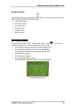
Page 27: ...attery screen UPS PROFILE SCREENS To see the UPS Profile screens from the Main Screen press once There are two UPS Profile screens The first UPS Profile screen shows Current date according to the UPS...

Page 28: ...e number of input and output phases For example 3 1 means 3 input phases and 1 output phase Version number of the PC701 card installed Version number of the PC705 card installed Second UPS Profile scr...

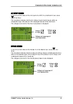
Page 29: ...ise an X is displayed instead of the checkmark The voltage and current for the three input phases is displayed BYPASS SCREEN To see the current status of the Bypass from the Main Screen press four tim...

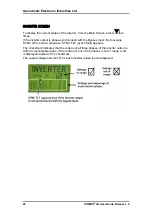
Page 30: ...is phase synchronized with the Bypass input the message SYNC OK is shown otherwise SYNC FLT synch fault appears The checkmark indicates that the voltage of all three phases of the inverter output is...

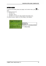
Page 31: ...ERY SCREEN To see the current battery status and voltages from the Main Screen press six times The battery status can be BATTERY OK BATTERY LOW or BATTERY FLT means the battery failed the latest batte...

Page 32: ...ures To display the Main Menu from the Main Screen press Ent POWER SA Main Menu The Main Menu options are described elsewhere in this book Event Log The event log displays current alarm conditions and...

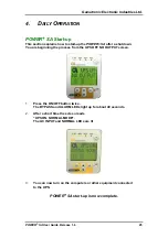
Page 33: ...shutdown You are beginning the process from the UPS OFF NO OUTPUT screen 1 Press the ON OFF button twice The BYPASS and ALARM LEDs light up for about 40 seconds 2 After a short time the screen reads...

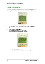
Page 34: ...o shut it down for a period of time during which the load devices will not be operating Begin the process from the UPS ON NORMAL MODE screen 1 It is advisable to turn of all equipment connected to the...

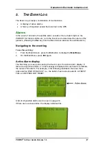
Page 35: ...the audible alarm Navigating to the event log To see the event log 1 From the Main Screen press the Ent button to display the Main Menu 2 On the Main Menu press Ent again Active Alarm display The firs...

Page 36: ...ning of the file so that the oldest events in the log are overwritten by the newest events The illustration shows a typical log entry The first line gives the number of the log entry This is the 23rd...

Page 37: ...load on the UPS this may resolve the problem If not contact Gamatronic Technical Support BATTERY LOW Meaning The battery will soon be fully discharged Additional indications The alarm LED lights up an...

Page 38: ...ghts up and the audible alarm sounds The symbol appears on the Inverter screen Action Contact Customer Support LOAD ON BYPASS Meaning The output voltage is the Bypass voltage Additional indications Ac...

Page 39: ...ul following a failed battery test END OF BACKUP Battery has been completely discharged RECHARGING Mains power has returned and battery is recharging INVERTER OFF The inverter has been turned off INVE...

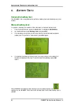
Page 40: ...t button to display the Main Menu 2 On the Main Menu select Battery Test and press Ent 3 The resulting screen tells you the time until the next scheduled automatic battery test To perform a manual tes...

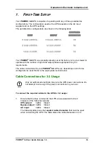
Page 41: ...S SE E O OF F 2 23 30 0V V 1 1 1 1 Your POWER SA UPS was probably already set at the factory or by your dealer to operate with the number of input and output phases appropriate for your requirements T...

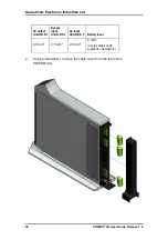
Page 42: ...r Guide Release 1 6 AC output Gnd N R S T Bypass input Gnd N R S T AC input Gnd N R S T Battery input 2 5 mm2 2 5 mm2 2 5 mm2 6 mm2 Use the battery cable supplied by Gamatronic 2 Using a screwdriver r...

Page 43: ...The uncovered rear panel is shown in the next illustration 3 Unplug the green plastic connectors and wire them as labelled Be sure the wires are not live before you begin Use wires of the proper diam...

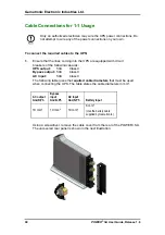
Page 44: ...cable to connect the battery to the UPS 6 Recheck the connections before continuing 7 To conceal and protect the cables and terminals replace the outside cover on the rear of the UPS Cable Connection...

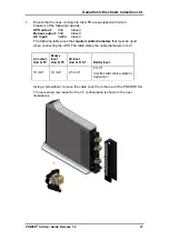
Page 45: ...The following table gives the required cable diameters that must be used when connecting the UPS The table states the cable diameters in mm2 AC output Gnd N Ph Bypass input Gnd N Ph AC input Gnd N R S...

Page 46: ...ut and Output cables to the terminals on the rear panel of the UPS Ensure the cables are not live before you begin For the Bypass input use the R phase for the Phase connection Use wires of the proper...

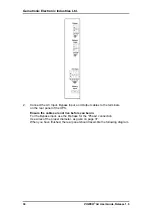
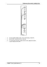
Page 47: ...R SA User Guide Release 1 6 39 3 Use the supplied battery cable to connect the battery to the UPS 4 Recheck the connections before continuing 5 To protect and conceal the cables and terminals replace...

Page 48: ...ith circuit breakers of the following capacity UPS output 50A Class C Bypass output 50A Class C AC input 50A Class C The following table gives the required cable diameters that must be used when conne...

Page 49: ...Connect the AC Input Bypass Input and Output cables to the terminals on the rear panel of the UPS Ensure the cables are not live before you begin Use wires of the proper diameter as given on page 37 W...

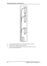
Page 50: ...OWER SA User Guide Release 1 6 8 Use the supplied battery cable to connect the battery to the UPS 9 Recheck the connections before continuing 10 To protect and conceal the cables and terminals replace...

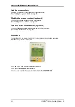
Page 51: ...hould see the following screen Verify proper number of input and output phases Before turning the UPS on for the first time verify that the UPS s setting for number of input and output phases is corre...

Page 52: ...contrast if necessary See Setting screen contrast on page 46 Set Automatic Restart mode optional You can enable automatic restart mode at this time if desired See Automatic Restart on page 50 Operati...

Page 53: ...K screen which shows the current time and date according to the POWER SA clock The information is displayed in the format HH MM SS DD MM YYYY 3 To change the time and date press Ent At any time in the...

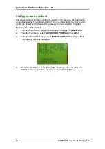
Page 54: ...n modify the default setting between the values of 0 and about 210 if needed To modify the console contrast 1 From the Main Screen press the Ent button to display the Main Menu 2 From the Main Menu se...

Page 55: ...not already in off mode press the ON OFF button twice to turn the UPS off 2 From the Main Screen press the Ent button to display the Main Menu 3 On the Main Menu choose ADVANCED OPTIONS and press Ent...

Page 56: ...une the UPS output voltage You can adjust each phase of the output voltage up and down by one or more volts if needed To change the nominal output voltage 1 From the Main Screen press the Ent button t...

Page 57: ...tage of the selected phase For example if the output voltage is currently 210 volts and you want to change it to 212 press the UP button twice to cause 2 to appear in the screen If you wanted to chang...

Page 58: ...c restart procedure when the AC power returns the recharging process begins automatically but no power is supplied to the load Determining the current automatic restart setting To determine if the aut...

Page 59: ...ronic Electronic Industries Ltd POWER SA User Guide Release 1 6 51 4 Press Ent to change the automatic restart status 5 The new automatic restart status is displayed Press Esc to return to the Main Sc...

Page 60: ...rmal Mode or Inverter Mode The input AC power bypasses the inverter entirely and goes directly to the load with no regulation This is called Bypass Mode Usually only a technician will need to manually...

Page 61: ...Gamatronic Electronic Industries Ltd POWER SA User Guide Release 1 6 53 On the Main Screen the message Manual Bypass appears in the lower right quadrant The audible alarm sounds after 60 seconds...

Page 62: ...If a power outage occurs 1 The Alarm LED lights up and the audible alarm sounds The UPS continues operating drawing its power from the batteries The POWER SA console looks like this The Alarm and Bat...

Page 63: ...computers connected to the UPS if you have not already done so When the UPS battery is exhausted the UPS does one of two things depending on the setting of Auto restart mode If Auto restart is DISABL...

Page 64: ...tries Ltd 56 POWER SA User Guide Release 1 6 If Auto restart is ENABLED and the battery is exhausted during a power outage the UPS screen goes blank and no LEDs are lit When AC power is restored the U...

Page 65: ...ternal circuit breaker for the AC line The circuit breaker may be off Battery Test failed It may be that an automatically scheduled battery test was executed shortly after the end of a power outage wh...

Page 66: ...POWER SA UPS system The dry contact circuits make use of opto couplers No more than 30V and 100mA should be applied to a dry contact The Alarm Dry Contacts can report any of three conditions as descr...

Page 67: ...nic Electronic Industries Ltd POWER SA User Guide Release 1 6 59 The following figure is a schematic of the Dry Alarm Contacts The triangles represent pins the numerals in the triangles represent pin...

Page 68: ...ere are two types of UPS connections Directly to a host computer with dedicated software Remote control through a SNMP WEB management programs for communication with a computer network optional In ord...

Page 69: ...nal Adaptor Internal Card The SNMP agent communicates with the RS232 interface of the UPS which Supports standard UPS RFC1628 MIB Supports the SNMP commands Trap Set and Get Transfers UPS indicators s...

Page 70: ...me time It is compatible with all Gamatronic products as well as with the products of many other manufacturers The WING comprises WING board A SIM board Application management software dedicated to wi...

Page 71: ...e power system every three seconds and alerts all the predefined recipients up to 10 recipients whenever a malfunction occurs The WING enables you to protect your system by 2 levels of passwords admin...

Page 72: ...Gamatronic Electronic Industries Ltd 64 POWER SA User Guide Release 1 6 WING Optional Configurations...

Page 73: ...tion Po 8KW 384W 1300 BTU Ambient temperature C 10 to 40 operating 20 to 70 storage Relative humidity 95 max non condensing Altitude m 1500 without derating Enclosure IP20 Cooling system Multi fan wit...

Page 74: ...olutions Headquarters and Factory 14 Hartom Street Science Based Industries Park POB 45029 Jerusalem 97774 Israel Tel Aviv Sales Office 34 Habarzel Street Ramat Hachayal Tel Aviv 69710 Israel Tel 972...

Reviews: