

12
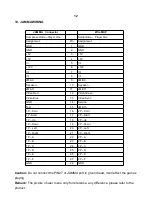
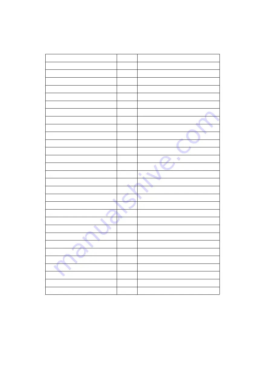
10. JAMMA WIRING
JAMMA Connector
Wire MAP
Component Side --Player One
Solder Side – Player Two
Assignment
Pin
Assignment
GND
1
GND
GND
2
GND
+5V
3
+5V
+5V
4
+5V
///
5
////
+12V
6
+12V
////
7
////
////
8
////
JMA 9
9
JMB 9
S
10
Speaker --
JMA 11
11
JMB 11
Video Red
12
Video Green
Video Blue
13
Video Sync.
GND
14
Service
Test
15
JMB 15
1P – Coin
16
2P – Coin
1P –Start
17
2P – Start
1P --Up
18
2P --Up
1P --Down
19
2P --Down
1P – Left
20
2P – Left
1P – Right
21
2P – Right
1P – A
22
2P – A
1P – B
23
2P – B
1P – C
24
2P – C
1P – D
25
2P – D
1P – E
26
2P – E
1P – F
27
2P – F
GND
28
GND
Caution:
Do not connect the PIN27 of JAMMA port to ground lead, it will affect the game’s
playing.
Remark:
The picture of user menu only for reference, any difference, please refer to the
product.
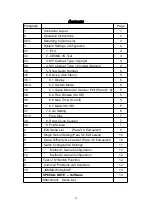
Summary of Contents for 412 in 1
Page 1: ...ELF 412 in 1 Arcade Game Board Manual ...
Page 7: ...4 ...


