9
HV1.7 ARGB (RAINBOW) HUB CONTROLLER
1. Product features
1
.
18 color models.
2
.
Mode and color adjustment.
3
.
Brightness adjustment.
(
can be Selection
)
4
.
SATA power supply.
5
.
Compatible with programmable RGB interface of
RAINBOW motherboard.
6. Can connect LED strip of ASUS.
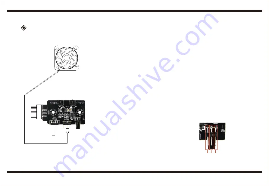
Schematic diagram of connection
- Switch mode
In the controller mode, press the MODE key 3S, and the white light
flickers. If you continue to press the key, the light will be turned off.
Press the MODE key again to turn on the light.
- Mode and color button
Short press one times mode and color button to change mode.Short
press two times mode and color buttons to change colors in the
same mode.
- Brightness button
Short press brightness button can adjust the brightness of LED.
This function depends on different versions to decide whether to
provide.
3. Interface definitions
3-1. ARGB
ARGB connect fan or light bar. The triangle mark on the plug is
aligned with the arrow on the controller.
3-2. MB ARGB
MB ARGB is connected to the motherboard ARGB interface.
The triangle mark on the plug is aligned with the arrow on the
controller.
3-3. SATA
SATA is the power supply interface and Output 5V DC voltage.
3-4. SW
SW is the switch interface. Some products have mode and
color control functions, and some products have brightness
adjustment function.
3-5. STRIP
Can connect lights strip of ASUS for 3PIN.
LED strip
connetor
Manual control switch
connetion port
Rainbow
connector
Connect
or t
o PSU
Motherboard
Rainbow
connector
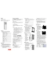
1
:
mode and color
2
:
GND
3
:
brightness
1 2
3
2. Functional description
2-1. Change MB and controller mode.
The default mode is controller mode. Press the MODE key for 3s,
and the white light flickers. It prompts you to switch into MB mode,
release the key and enter the MB mode. After entering the MB mode,
press the MODE key and enter the controller mode again.
2-2. Switch mode
In the controller mode, press the MODE key 3S, and the white light
flickers. If you continue to press the key, the light will be turned off.
Press the MODE key again to turn on the light.
2-3. Memory function.
This controller has memory function.
2-4. Mode and color button.
Short press one time mode and color button to change mode.
Short press two times mode and color button to change colors in the
same mode.
2-5. Brightness button
Short press brightness button can adjust the brightness of LED.
This function depends on different versions to decide whether to
provide.
2-6. AURA SYNC
After connecting the interface, the light control of the MB can be
realized by key-press operation.
2-7. Strip
It can be connected LED strip with ASUS standard.


