Flex 620 System Operation - Revision 5, 11/22/01
_______________________________________________________________________________________________
21
BYPASS
Programming
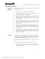
Bypass is used to disable input and output circuits. To use the Bypass option, enter
the proper Access level and press the Bypass key. The LED will flash at a fast rate
indicating that you are in the Bypass circuit selection mode. Select the desired input
and output circuits to be Bypassed and press the Bypass key again. The selected
circuit(s) and Bypass LEDs should flash at the same rate indicating the circuits are
Bypassed. To deselect circuits, press the Bypass switch (Bypass LED Flashes fast)
Deselect circuits and press the Bypass switch again. Circuits deselected will
extinguish.
A. Input Points Bypassed
When the Bypass is utilized it will disable an input circuit that is damaged
and cannot be cleared.
B. Output Signal Circuit Bypassed
Programming any output signal circuit to Bypass will disable the circuit from
activating.
C. Output Relay Circuits bypassed
Programming any output relay circuit to Bypass will disable the circuit from
activating.
D. Building Control Circuits bypassed
Programming any building control circuit to Bypass will disable the circuit
from activating.
E. City Tie(s) bypassed
Programming any City Tie circuit to Bypass will disable the circuit from the
transmitting alarm.
WALKTEST
Programming
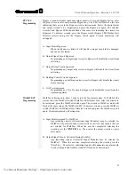
WalkTest is designed to allow 1 man to test the fire alarm system. To WalkTest the
system select the WalkTest switch (WalkTest LED flashes fast), select the circuits to
be tested and press the WalkTest switch again. The circuits in WalkTest mode will
flash at the same rate as the WalkTest LED. To deselect circuits, press the WalkTest
switch (WalkTest LED Flashes fast) Deselect circuits and press the WalkTest switch
again. Circuits deselected will extinguish.
A. Input Points Assigned To WalkTest
Any initiating circuits (Conventional Input Modules) may be selected for
WalkTest. Any selected Input circuits will not activate any outputs that are
not selected for WalkTest. When the user has completed selecting the
circuits press the "
ENTER
" key. Then select the output circuits or press
enter again.
B. Output Signal Circuits Activated During WalkTest
Any indicating circuits (Universal Signal Modules) may be selected for
WalkTest. When the user has completed selecting the circuits press the
"Enter" key. The selected indicating signals will annunciate any alarm with
two short outputs and troubles created will sound one short output.
Technical Manuals Online! - http://www.tech-man.com
Summary of Contents for FLEXALARM 620
Page 2: ...This page intentionally blank Technical Manuals Online http www tech man com...
Page 4: ...This page intentionally blank Technical Manuals Online http www tech man com...
Page 6: ...This page intentionally blank Technical Manuals Online http www tech man com...
Page 7: ...Technical Manuals Online http www tech man com...
Page 8: ...This page intentionally blank Technical Manuals Online http www tech man com...
Page 12: ...Technical Manuals Online http www tech man com...
Page 13: ...This page intentionally blank Technical Manuals Online http www tech man com...
Page 20: ...Technical Manuals Online http www tech man com...
Page 21: ...Section 2 FLEXALARM 620 System Operation Technical Manuals Online http www tech man com...
Page 34: ...Technical Manuals Online http www tech man com...
Page 35: ...This page intentionally blank Technical Manuals Online http www tech man com...
Page 64: ...Technical Manuals Online http www tech man com...
Page 65: ...Section 4 FlexAlarm 620 Programming Technical Manuals Online http www tech man com...


