Flex 620 System Operation - Revision 5, 11/22/01
_______________________________________________________________________________________________
40
Universal
Signal Circuit
Module
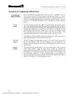
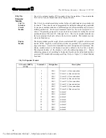
The indicating signal circuit modules (USM-4, USM-8) consists of up to three (3)
assemblies. The
I/O Signal Module
,
Style "Z" Adapter
, and the
Alarm Display Card
.
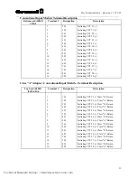
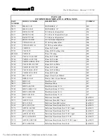
To view a comprehensive listing of compatible devices with the Flex 620 control
panel, refer to Figure I-4, Compatible Indicating Appliances found at the end of this
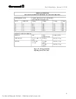
section. Also reference to Figure I-5, Wiring Guidelines Signaling Circuit Wire Sizes.
Signal Circuit
Module
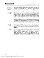
The signal circuit module provides four (4) or eight (8), 2 amp DC, current limited
analog signaling circuits. All circuits operate on the Style Y (Class B) mode of
operation. The end of line resistor (EOLR) is 3.9K ohm. Programming jumper (S1)
is provided on each board for setting the vertical position/address of the card (J1
through J4). The I/O signal module uses the lower terminal block and connects via
cable to the bus driver module. Each universal signal module communicates via the
Module bus and requires one bay position each.
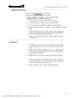
The SIGNAL I/O board has an option that allows programming of the signal circuits
to be operable under Default Alarm Mode. A DIP switch (S2) is provided on the
module to select which signaling circuits operate under default alarm mode. To set
the circuits that are active, close their respective switch on S2. I.E.: Switch 1 for
circuit 1, Switch 2 for circuit 2, through Switch 8 for circuit 8.
Style "Z"
Adapter
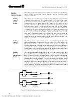
The Style D adapter (USM-SZA) card provides four (4) or eight (8) Style Z (Class A)
circuits to the I/O signal card. When the Style Z adapter is used the EOLR's are not
required. The Style Z adapter uses the upper terminal block, and is cabled to the I/O
signal module.
Display
Module
The alarm display module provides eight (8) red zone alarmed LED's, eight (8) yellow
zone trouble LED's. Eight (8) zone tactile switches are provided for
programming
,
Bypass
and
WalkTest
functions. Card slots are furnished for zone description,
comments. The display module connects (via the display bus) to the bus driver
module. The physical location of the display is set by the addressing jumper S1.
Ensure addressing jumper is set according to its physical location in the cabinet and
matches associated I/O module address jumper setting. Refer to Figure I-1, Cabinet
Module Locations.
Technical Manuals Online! - http://www.tech-man.com
Summary of Contents for FLEXALARM 620
Page 2: ...This page intentionally blank Technical Manuals Online http www tech man com...
Page 4: ...This page intentionally blank Technical Manuals Online http www tech man com...
Page 6: ...This page intentionally blank Technical Manuals Online http www tech man com...
Page 7: ...Technical Manuals Online http www tech man com...
Page 8: ...This page intentionally blank Technical Manuals Online http www tech man com...
Page 12: ...Technical Manuals Online http www tech man com...
Page 13: ...This page intentionally blank Technical Manuals Online http www tech man com...
Page 20: ...Technical Manuals Online http www tech man com...
Page 21: ...Section 2 FLEXALARM 620 System Operation Technical Manuals Online http www tech man com...
Page 34: ...Technical Manuals Online http www tech man com...
Page 35: ...This page intentionally blank Technical Manuals Online http www tech man com...
Page 64: ...Technical Manuals Online http www tech man com...
Page 65: ...Section 4 FlexAlarm 620 Programming Technical Manuals Online http www tech man com...


