background image

4

FocalPoint™ Receivers Gateway


Installation & Operation Manual

 - 

P/N: 53251

:

Rev: A


9/8/09

LIMITATIONS OF FIRE ALARM SYSTEMS

Gamewell/FCI recommends that smoke and/or heat 
detectors be located throughout the protected premises 
following the recommendations of the current edition of the 
National Fire Protection Association Standard 72, the 
National Fire Alarm Code (NFPA 72), manufacturer’s 
recommendations, State and local codes, and the 
recommendations contained in the Guide for the Proper 
Use of System Smoke Detectors, which is made available 
at no charge to all installing dealers.  A study by the Federal 
Emergency Management Agency (an agency of the United 
States government) indicated that smoke detectors may not 
go into alarm or give early warning in as many as 35% of all 
fires.  While fire alarm systems are designed to provide 
warning against fire, they do not guarantee warning or 
protection against fire.  Any alarm system is subject to 
compromise or failure to warn for a variety of reasons.  For 
example:
Particles of combustion or “smoke” from a developing fire 
may not reach the sensing chambers of a smoke detector 
because:

Barriers such as closed or partially closed doors, walls, 
or chimneys may inhibit air flow.

Smoke particles may become “cold” and stratify, and 
may not reach the ceiling or upper walls where 
detectors are located.

Smoke particles may be blown away from detectors by 
air outlets.

Smoke particles may be drawn into air returns before 
reaching the detector.

In general, smoke detectors on one level of a structure 
cannot be expected to sense fires developing on another 
level.
The amount of “smoke” present may be insufficient to alarm 
smoke detectors.  Smoke detectors are designed to alarm 
at various levels of smoke density.  If such density levels 
are not created by a developing fire at the location of 
detectors, the detectors will not go into alarm.
Smoke detectors, even when working properly, have 
sensing limitations.  Detectors that have photo-electronic 
sensing chambers tend to detect smoldering fires earlier 
than flaming fires, which have little visible smoke.  
Detectors that have ionization-type sensing chambers tend 
to detect fast flaming fires earlier than smoldering fires.  
Because fires develop in different ways and are often 
unpredictable in their growth, neither type of detector is 
necessarily best and a given type of detector may not 
provide adequate warning of a fire.
Smoke detectors are subject to unwanted or nuisance 
alarms.  For example, a smoke detector located in or near a 
kitchen may go into nuisance alarm during normal 
operation of kitchen appliances.  In addition, dusty or 
steamy environments may cause a smoke detector to alarm 
unnecessarily.  If the location of a smoke detector causes 
an abundance of unwanted or nuisance alarms, do not 
disconnect the smoke detector; call a professional to 
analyze the situation and recommend a solution.  
Smoke detectors cannot be expected to provide adequate 
warning of a fire caused by arson, children playing with 
matches (especially in bedrooms), smoking in bed, violent 

explosions (caused by escaping gas, improper storage of 
flammable materials, etc.).
Heat detectors do not sense particles of combustion and 
are designed to alarm only when heat on their sensors 
increase at a predetermined rate or reaches a 
predetermined level.  Heat detectors are designed to 
protect property, not life.
Warning devices (including horns, sirens, bells, and 
speakers) may not alert people or awaken sleepers who 
are located on the other side of closed or partially open 
doors.  A warning device that activates on a different floor 
or level of a dwelling or structure is less likely to awaken or 
alert people.  Even persons who are awake may not notice 
the warning if the alarm is muffled by noise from a stereo, 
radio, air conditioner or other appliance, or by passing 
traffic.  Audible warning devices may not alert the hearing-
impaired (strobes or other devices should be provided to 
warn these people).  Any warning device may fail to alert 
people with a disability, deep sleepers, people who have 
recently used alcohol or drugs, or people on medication or 
sleeping pills.
Please note that:

Strobes can, under certain circumstances, cause 
seizures in people with conditions such as epilepsy.

Studies have shown that certain people, even when 
they hear a fire alarm signal, do not respond or 
comprehend the meaning of the signal.  It is the 
property owner’s responsibility to conduct fire drills and 
other training exercises to make people aware of the 
fire alarm signals and instruct on the proper reaction to 
alarm signals.

In rare instances, the sounding of a warning device 
can cause temporary or permanent hearing loss.

Telephone lines needed to transmit alarm signals from a 
premise to a central station may be out of service or 
temporarily out of service.  For added protection against 
telephone line failure, backup radio transmission systems 
are recommended.
System components, though designed to last many years, 
can fail at any time.  As a precautionary measure, it is 
recommended that smoke detectors be checked, 
maintained, and replaced per manufacturer’s 
recommendations.
System components will not work without electrical power.  
If system batteries are not serviced or replaced regularly, 
they may not provide adequate standby when AC power 
fails.
Environments with high air velocity or that are dusty or dirty 
require more frequent maintenance.
In general, fire alarm systems and devices will not work 
without power and will not function properly unless they are 
maintained and tested regularly.
While installing a fire alarm system may make the owner 
eligible for a lower insurance rate, a fire alarm system is not 
a substitute for insurance.  Property owners should 
continue to act prudently in protecting the premises and the 
people on the premises and should properly insure life and 
property and buy sufficient amounts of liability insurance to 
meet their needs.

Summary of Contents for FPT-DACR-GW

Page 1: ...06472 203 484 7161 FAX 203 484 7118 www gamewell fci com FocalPoint System Utilities User s Guide FocalPoint Receivers Gateway Installation Operation Manual Copyright 2009 All Rights Reserved Publishe...

Page 2: ...n which the Authority Having Jurisdiction requires If you do not know which authority has jurisdiction in your area contact your local fire department or building inspector for guidance It is importan...

Page 3: ...ards and applicable state and local codes At a minimum the requirements of Chapter 7 of NFPA the National Fire Alarm Code shall be followed A preventative maintenance agreement should be arranged thro...

Page 4: ...on and recommend a solution Smoke detectors cannot be expected to provide adequate warning of a fire caused by arson children playing with matches especially in bedrooms smoking in bed violent explosi...

Page 5: ...e IDs 13 2 3 Radionics D6600 Setup 14 2 3 1 D6600 Description 14 Figure 2 2 Radionics D6600 Receiver Application Example 14 2 3 2 Supported Formats 14 2 3 3 D6600 Serial Communication Connection 15 Fi...

Page 6: ...munication Configuration 24 3 4 1 Establish Receivers Gateway Workstation Communication 24 3 4 2 Receivers Gateway s Port Configuration 25 Section 4 Receivers Gateway Reference Information 27 4 1 Layo...

Page 7: ...Gateway is capable of monitoring up to 20 digital alarm receivers Supported receiver types are ADEMCO 685 Radionics D6600 Silent Knight 9500 9800 Teldat VisorALARM Supported protocols for these receiv...

Page 8: ...t is intended to be installed in accordance with the following regulatory agencies FocalPoint Receiver Gateway Ethernet Digital Alarm Receiver Telephone Dialer FocalPoint Components Ethernet FACP NOTE...

Page 9: ...Part I Safety Standard for Electrical Installations 1 4 Environmental Requirements This product must be installed in the following environmental conditions Temperature range of 0 C to 49 C 32 F 120 F...

Page 10: ...About Receivers Gateways Related Documentation 10 FocalPoint Receivers Gateway Installation Operation Manual P N 53251 Rev A 9 8 09...

Page 11: ...g units Every device that calls a receiver must have an account code that uses a supported protocol Each account code must be unique throughout the entire system Each device or panel must utilize the...

Page 12: ...there is a DIP switch set the switches as Switch 4 PRN OFF PRN Off Switch 8 OFF COM OFF Off 2 2 4 685 Supported Formats The supported address format is ADEMCO Contact ID 2 2 5 685 Parallel Printer Req...

Page 13: ...the native format or be very similar In all cases field tests should be performed to confirm the reported format of panel devices 2 2 9 685 Site IDs When using dialers to communicate with the 685 rec...

Page 14: ...rouble event information that can be used in conjunction with a Workstation and other FocalPoint clients The Radionics D6600 receiver is a modular multi format digital receiver designed to receive dis...

Page 15: ...fer to the table below for D6600 settings For more detailed information see the Radionics D6600 Program Entry Guide Workstation Receivers Gateway D6600 Unused COM Port COM DB9 connector to non dedicat...

Page 16: ...hen the D6600 is OK The D6600 knows that the Receivers Gateway is OK if it received the Gateway s reply to the message that it sent 2 3 6 D6600 Operation and Event Handling Device Addresses as Reporte...

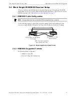
Page 17: ...es on page 11 2 4 1 9500 9800 Cable Configuration Use the following figure to configure the serial cable running from the automation port of the receiver to a non dedicated COM port of the PC on which...

Page 18: ...iver sites are supervised by the Workstation Panels connected to receivers generate a periodic test message The Receivers Gateway uses that test message to supervise the site In the Gateway s configur...

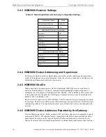
Page 19: ...l devices reported by Silent Knight 9500 9800 receivers to fit the FocalPoint system format of an 8 character point ID Since there is no actual node or sub node located at the panel the Gateway always...

Page 20: ...tion computer Figure 2 5 VisorALARM Cable Connections 2 5 2 VisorALARM Serial Communication Connection The VisorALARM also connects via an Ethernet cable into the intranet where it can receive events...

Page 21: ...sing and Supervision Receivers Gateway monitors the VisorALARM for trouble conditions and reports them to connected Workstations The Workstation will auto create an icon for this receiver and will dis...

Page 22: ...Digital Receivers Installation and Configuration Teldat VisorALARM Receiver Setup 22 FocalPoint Receivers Gateway Installation Operation Manual P N 53251 Rev A 9 8 09...

Page 23: ...tings Refer to Receivers Gateway Network Communication Configuration on page 24 System Limitations Each instance of the Receivers Gateway can support a maximum of 20 receivers 3 2 Workstation Startup...

Page 24: ...curity Profiles 3 3 1 Closing and Shutting Down the Gateway File Close will minimize the Receivers Gateway screen the Receivers Gateway is still running and its icon appears in the System Tray File Sh...

Page 25: ...pe in the Gateway s IP Address Select a gateway from the list of Online Gateways Step 8 Click on the OK button Step 9 Exit the Configuration Tool and respond to the confirmation window prompt Yes mean...

Page 26: ...Receivers Gateway Installation and Configuration Receivers Gateway Network Communication Configuration 26 FocalPoint Receivers Gateway Installation Operation Manual P N 53251 Rev A 9 8 09...

Page 27: ...s will be reported to the Workstation and appear in the Events Box like any other FocalPoint system event Refer to the FocalPoint Workstation manual for details concerning the Events Box and event han...

Page 28: ...ies Monitoring FPT Receivers Gateway The FPT Receivers Gateway window displays Step 2 From its menu select File Login The User Login window displays Step 3 Click on to highlight a user name that has a...

Page 29: ...RAM OK Report as event Program Exit on device PROG with device type Processor X 47 REMOTE SOFTWARE PROGRAM IN Report as event Program Entry on device PROG with device type Processor X 48 REMOTE SOFTWA...

Page 30: ...port as event Offline Restored on device AUDIO LINE with device type Audio System X 62 DATA ERROR LINE Report as event Advise on device E62 L LINE with device type Telephone X 62 NO DATA RECEIVED LINE...

Page 31: ...NTERCEPT Report as event Device Re enabled on device C900INTR with device type Communication X 82 C900 SWITCHED TO FALLBACK Report as event Device Disabled on device C900INTR with device type Communic...

Page 32: ...e type Communication X 75 NO RESPONSE TO ACK Report as event Advise on device EVENT 75 with device type Communication X 76 MESSAGE UNKNOWN Report as event Advise on device EVENT 76 with device type Co...

Page 33: ...e Detector Smoke 112 ZONE G ZO GROUP Combo Detector Combustion 113 ZONE G ZO GROUP Waterflow Water flow 114 ZONE G ZO GROUP Heat Detector Heat 115 ZONE G ZO GROUP Pullstation Pull Station 116 ZONE G Z...

Page 34: ...urg 151 ZONE G ZO GROUP Gas Leak Detector Gas detected 152 ZONE G ZO GROUP Leak Detector Refrigeration 153 ZONE G ZO GROUP Heat Detector Loss of heat 154 ZONE G ZO GROUP Waterflow Water Leakage 155 ZO...

Page 35: ...Power Supply Power Supply Overcurrent 313 SRVC G SR GROUP Zone Engineer Reset User 314 ACPWR G AC GROUP Power Supply Primary Power Supply Failure 320 RELAY G RE GROUP Audible Output Sounder Relay 321...

Page 36: ...ault 354 COMM G CO GROUP Communication Fail to communicate 355 RFSUP G RF GROUP Communication Loss of radio supervision 356 RFPOL G RF GROUP Communication Loss of central polling 357 ZONE G ZO GROUP P...

Page 37: ...GROUP Control Panel Primary Receiver Active 397 COMM G CO GROUP Communication Primary Receiver Down 398 DACR G DA GROUP Control Panel Backup Receiver Active 399 DACR G DA GROUP Control Panel Receiver...

Page 38: ...O GROUP Zone Access threat level change 432 ZONE G ZO GROUP Zone Access relay trigger fail 433 ZONE G ZO GROUP Zone Access RTE shunt 434 ZONE G ZO GROUP Zone Access DSM shunt 435 ZONE G ZO GROUP Door...

Page 39: ...eneric Control Output Reversing relay disable 526 NAC3 G NA GROUP Common Bell Output Notification Appliance Ckt 3 disable 527 NAC4 G NA GROUP Common Bell Output Notification Appliance Ckt 4 disable 53...

Page 40: ...616 ZONE G ZO GROUP Zone Service Request 621 ZONE G ZO GROUP Zone Event Log reset 622 ZONE G ZO GROUP Control Panel Event Log 50 full 623 ZONE G ZO GROUP Control Panel Event Log 90 full 624 PANEL G P...

Page 41: ...ZO GROUP Control Panel System Inactivity 900 ZONE G ZO GROUP Control Panel Download Abort 901 ZONE G ZO GROUP Control Panel Download Start 902 ZONE G ZO GROUP Control Panel Download Interrupt 910 ZON...

Page 42: ...Contact ID Reporting Formats 42 FocalPoint Receivers Gateway Installation Operation Manual P N 53251 Rev A 9 8 09...

Page 43: ...way System Architecture 7 H Help 28 About 28 I Installation Environmental Conditions 9 L Login 28 N Network Clients 28 R Radionics D6600 Receiver 14 D6600 Configuration 15 Device IDs 16 Event Handling...

Page 44: ...Index 44 FocalPoint Receivers Gateway Installation Operation Manual P N 53251 Rev A 9 8 09...

Page 45: ...ECT TO THE PRODUCTS TRADEMARKS PROGRAMS AND SERVICES RENDERED BY MANUFACTURER INCLUDING WITHOUT LIMITATION INFRINGEMENT TITLE MERCHANTABILITY OR FITNESS FOR ANY PARTICULAR PURPOSE MANUFACTURER SHALL N...

Page 46: ...Gamewell FCI 12 Clintonville Road Northford CT 06472 1610 USA 203 484 7161 fax 203 484 7118 www gamewell fci com...

Reviews: