IF 610 Installation and Operation Manual
Issue 3, 10/04/00
Firmware Ver. 7
30
Signal Circuit 1
Signal CCT#1, 24V@2A, Style Y or Z
Style Y requires 3.9K ohm end of the line
resistor.
1L1R
Style Z (-) Return
1L1
(-) Signal Power
1L2
(+) Signal Power
1L2R
Style Z (+) Return
Signal Circuit 2
Signal CCT#2, 24V@2A, Style Y or Z
Style Y requires 3.9K ohm end of the line
resistor.
2L1R
Style Z (-) Return
2L1
(-) Signal Power
2L2
(+) Signal Power
2L2R
Style Z (+) Return
* NOTE: Total load of regulated power including system power,
A+A- and S+S- must not exceed 2 Amps.
** NOTE: Style Y signal circuit wiring requires 3.9k EOL Resistor.
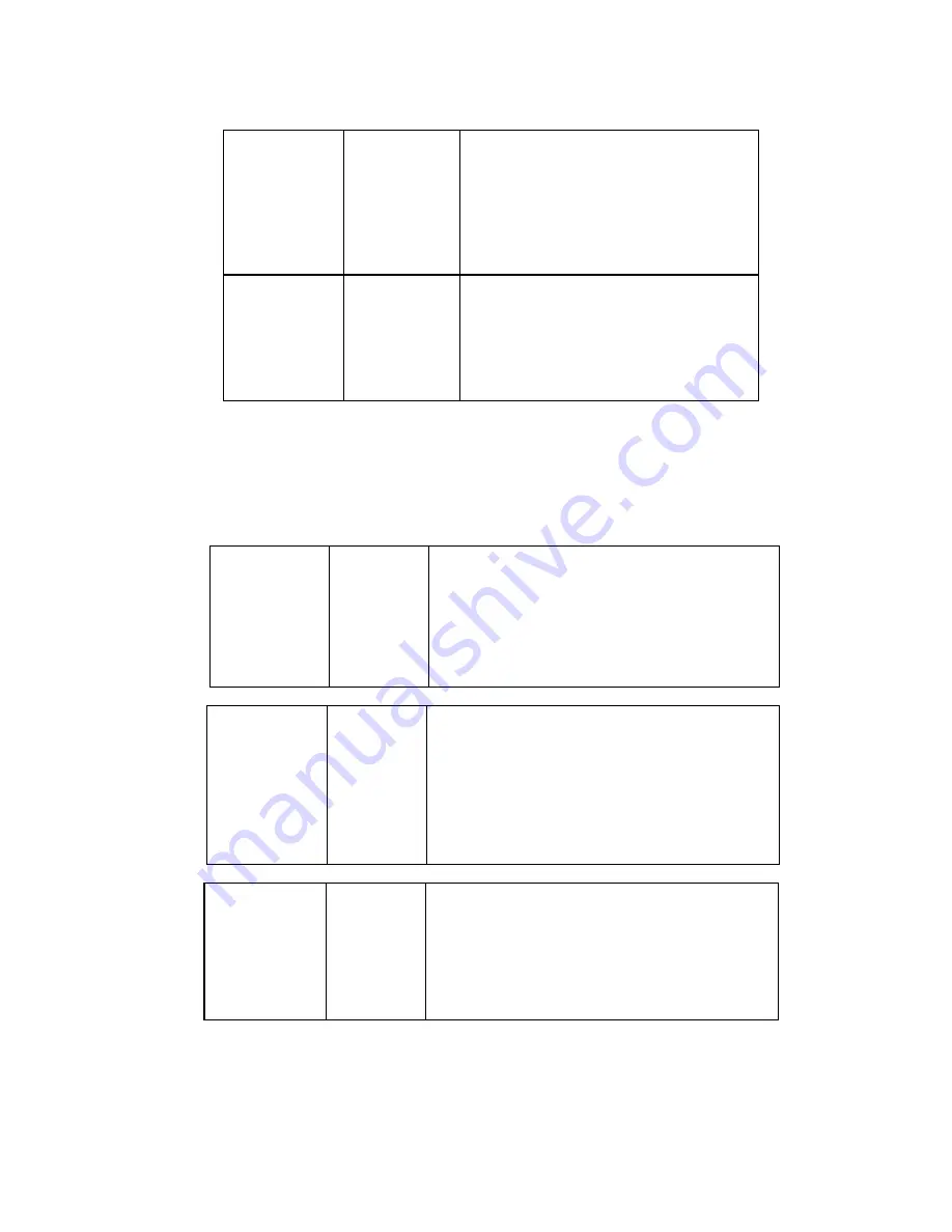
Relays
RELAY 1
COMMON
ALARM
Designation Description
1 NO
Form C normally open Alarm contact
1 NC
Form C normally closed Alarm contact
1 C
Form C Alarm relay common contact 2.0A @ 30
VDC or 120 VAC @ 1.0 amps.
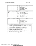
RELAY 2
COMMON
TROUBLE
Designation
* Relay is shown normally energized (normal
condition)
2 NO
De-energizes on Trouble, restores when Trouble is
remedied
2 NC
Form C normally closed Trouble contact
2 C
Form C Trouble relay common contact 2.0A @ 30
VDC or 120 VAC @ 1.0 amps.
RELAY 3
COMMON
SUPERVISORY
Designation Description
3 NO
Form C normally open Supervisory contact
3 NC
Form C normally closed Supervisory contact
3 C
Form C Supervisory relay common contact 2.0A @
30 VDC or 120 VAC @ 1.0 amps.
Technical Manuals Online! - http://www.tech-man.com
firealarmresources.com


