IF 610 Installation and Operation Manual
Issue 3, 10/04/00
Firmware Ver. 7
31
RELAY 4
SPARE
Designation Description
4 NO
Form C normally open spare contact
4 NC
Form C normally closed spare contact
4 C
Form C spare relay common contact 2.0A @ 30
VDC or 120 VAC @ 1.0 amps.
ISO 232
Designation
Description
XMT
RS-232
Out
Term.
RCV
RS-232 Input
Strip
C
Common (logic) ground
GND
Earth
Ground
ISO 232
Description
RS-232
Input
Telephone
RS-232 Output
Jack
NC
Common (logic) ground
Analog Interface Module & Subassembly Specifications
Analog Addressable
Interface Module
This module drives one, two or four circuits that can monitor and control up to
126 analog addressable devices (points) per line for a total of 504. The functions
of this card are controlled by a micro controller and the software programming.
The system uses a 6 point, removable, field wiring terminal strip for each circuit
provided..
The analog interface board with the micro controller and one circuit driver
circuits draws 26mA from the 24V supply, the two circuit card draws 35ma and
the four circuit card brings the current draw to 55mA, excluding any draw by
devices on the lines.
Installation
Diagram
Refer to drawing C-M818 (Assembly of IF 610 Cabinet) for installation and
drawing D-W1175 (Wiring IF 610 System) for cable connections.
Analog Addressable Card
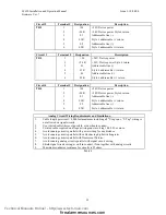
Circuit 1
Terminal #
Designation
Description
TB-1
1
+24
+24V Device power
2
+24 R
+24V Device power Style 6 return
3
L1
Addressable line (-)
4
L1R
Style 6 addressable (-) return
5
L2
Addressable line (+)
6
L2R
Style 6 addressable (+) return
Technical Manuals Online! - http://www.tech-man.com
firealarmresources.com


